
Line shafting
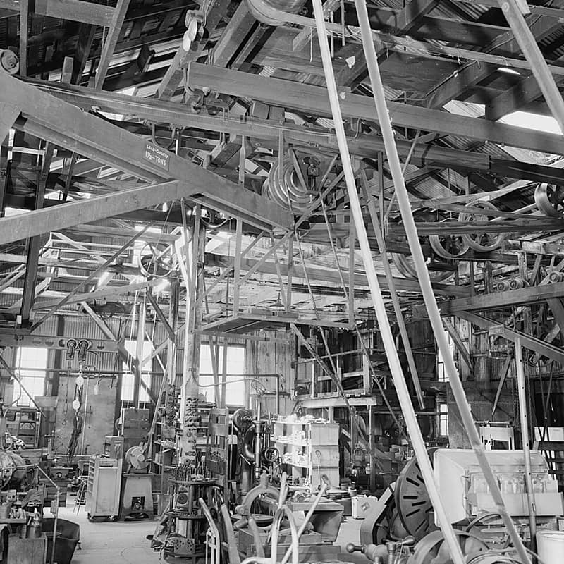
A works of this period often had one engine or one water wheel, and the machines in it took its power from a turning iron bar overhead. How to run a line in the game is in the shaft power guide. This page is about the real shafting, why it looked as it did, and how far the game follows it.
One prime mover, and why the shaft exists at all
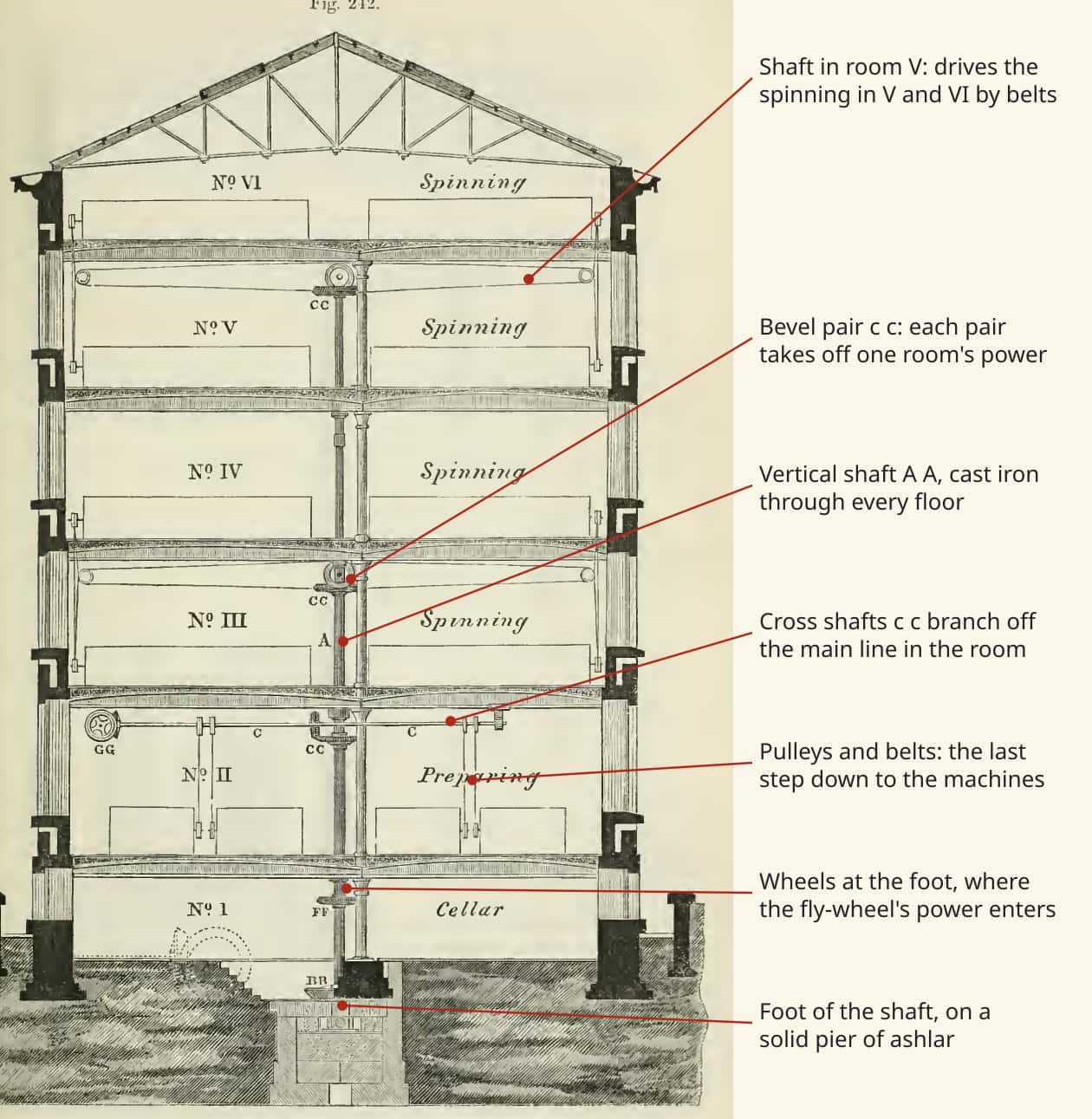
Before steam, a mill often had a water wheel for every machine or pair of machines (Fairbairn Mills II p. 50). Concentrating the prime movers saved water and then fuel, and it needed a way of carrying power across a building. That way was shafting, and Fairbairn traces the whole factory system to it: any number of processes under one roof, moved by a single engine at a convenient distance, through "lines of shafting coupled together in lengths, adapted to the bays or divisions of the building" (Fairbairn Mills II p. 50). Lines of 200 or 300 ft followed, and the shafting at Saltaire laid end to end would have run more than two miles (Fairbairn Mills II pp. 50-51).
The arrangement had a cost that every mill paid. A line of shafting turns whether or not the machines on it are working, and a long one is a load in its own right. Fairbairn says the ponderous shafts of about 1800, "generally of cast iron, square, and badly coupled", took in some cases almost as much power to turn as the machines they drove (Fairbairn Mills II p. 72).
Fast and thin, or slow and heavy
A shaft carries power as turning force times speed, so the same power at twice the speed needs half the turning force and a thinner bar. Fairbairn built his career on that: he credits his success to "increasing threefold the velocity of the shafting" (Fairbairn Mills II p. 72), and says a shaft at 50 revolutions a minute needs fully three times the weight of one doing the same work at the speed he recommends, about half that of the machines (Fairbairn Mills II p. 72). Slow shafts also block a room with large drums and pulleys and take away the light (Fairbairn Mills II p. 72).
The material followed the job. Wood with iron hoops was first and by Fairbairn's day obsolete. The main and vertical shafts stayed cast iron, which was cheap, stiff and good in torsion, and wrought iron took over the line shafting and wherever there was impact (Fairbairn Mills II p. 51). A long shaft was sized by what it bent as much as by what it could carry: no more than 1/1200 of its length under load, since "a stiff shaft, although heavier in itself, is lighter to retain in motion than a smaller one which bends" (Fairbairn Mills II pp. 60-61).
Lengths, and how they were joined and held
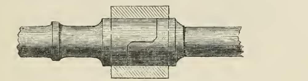
Shafts were cast or rolled in lengths and joined by the bay. The earliest joints were a square box slipped over two square ends, which rose and fell at every turn and wore out its own fit; the claw coupling, Hewes's half-lap with three keys, and the bolted disc followed (Fairbairn Mills II pp. 79-80). Fairbairn's own circular half-lap replaced them for general work, and he calls it "the most accurate and durable" (Fairbairn Mills II p. 81). A butt-ended cylinder coupling of the same proportions was cheaper, and weaker, since all the torque went through the key (Fairbairn Mills II p. 82).
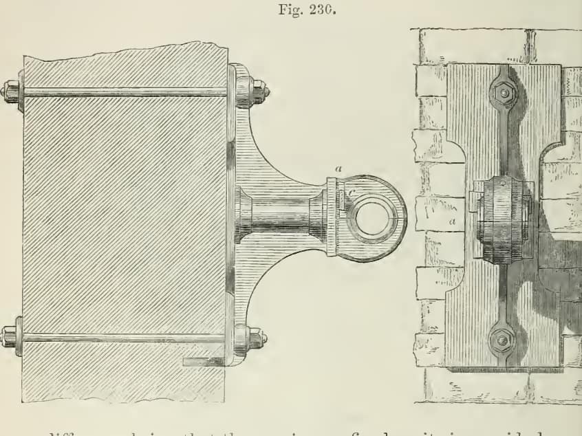
Each bearing was a plummer block: a cast seat, a cap, and brass steps round the journal. Journals ran one and a half diameters long for cast iron and one and three-quarters for wrought (Fairbairn Mills II p. 73), and the collars next to them were to be hollowed and never cut square, since a square shoulder cost the shaft strength (Fairbairn Mills II p. 74). Oil was the running cost. The oiling of shafts was "generally left to the most negligent and most untidy person in the establishment", and in a large cotton mill a change in the quality of the oil could absorb ten to fifteen horse-power; the power needed on a Monday morning, after a cold Sunday, was always higher than on any other day (Fairbairn Mills II pp. 77-78). Fairbairn's preferred oiler was a small cistern on the plummer block feeding the journal through a woollen thread (Fairbairn Mills II p. 78).
Turning a corner: bevel wheels
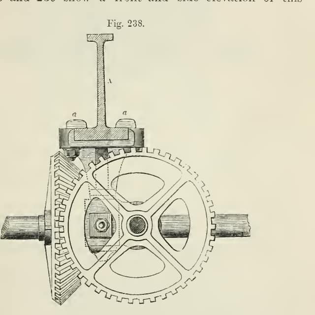
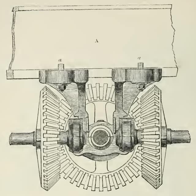
Toothed wheels did the turning and the changing of speed. Lancashire and Yorkshire preferred them for the whole run, and American mills drove from a great drum by leather straps; Fairbairn found less journal friction with gearing, but agreed straps suited irregular work and the last step from shaft to machine, since they slip as they wear, which loses time and eases shocks (Fairbairn Mills II pp. 1-3). Gears set the speed too: a small mill's spur fly-wheel on a pinion "nearly doubled" the speed on its main shaft (Fairbairn Mills II p. 123), and at Taganrog a fly-wheel of 24 ft 5 in at 24.7 rpm drove a pinion at 87.7, a step of about 3.5 (Fairbairn Mills II pp. 127-128).
Flywheels and letting go
Between the strokes of an engine and the bites of a mill the demand on a shaft changes quickly, and a rotating mass smooths it: a heavy rim gives up a little speed when the load comes on and takes it back when the load goes off. An engine's fly-wheel did that job, and in an iron mill it did it hardest. Plate rolling wanted "the momentum of a large fly-wheel" to carry the plates through the rolls, and even then thin plates could cool before they were done (Fairbairn Mills II p. 259).
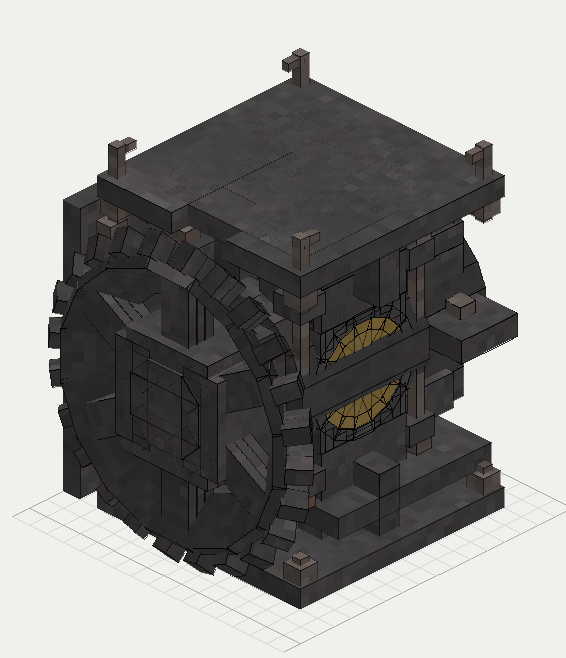
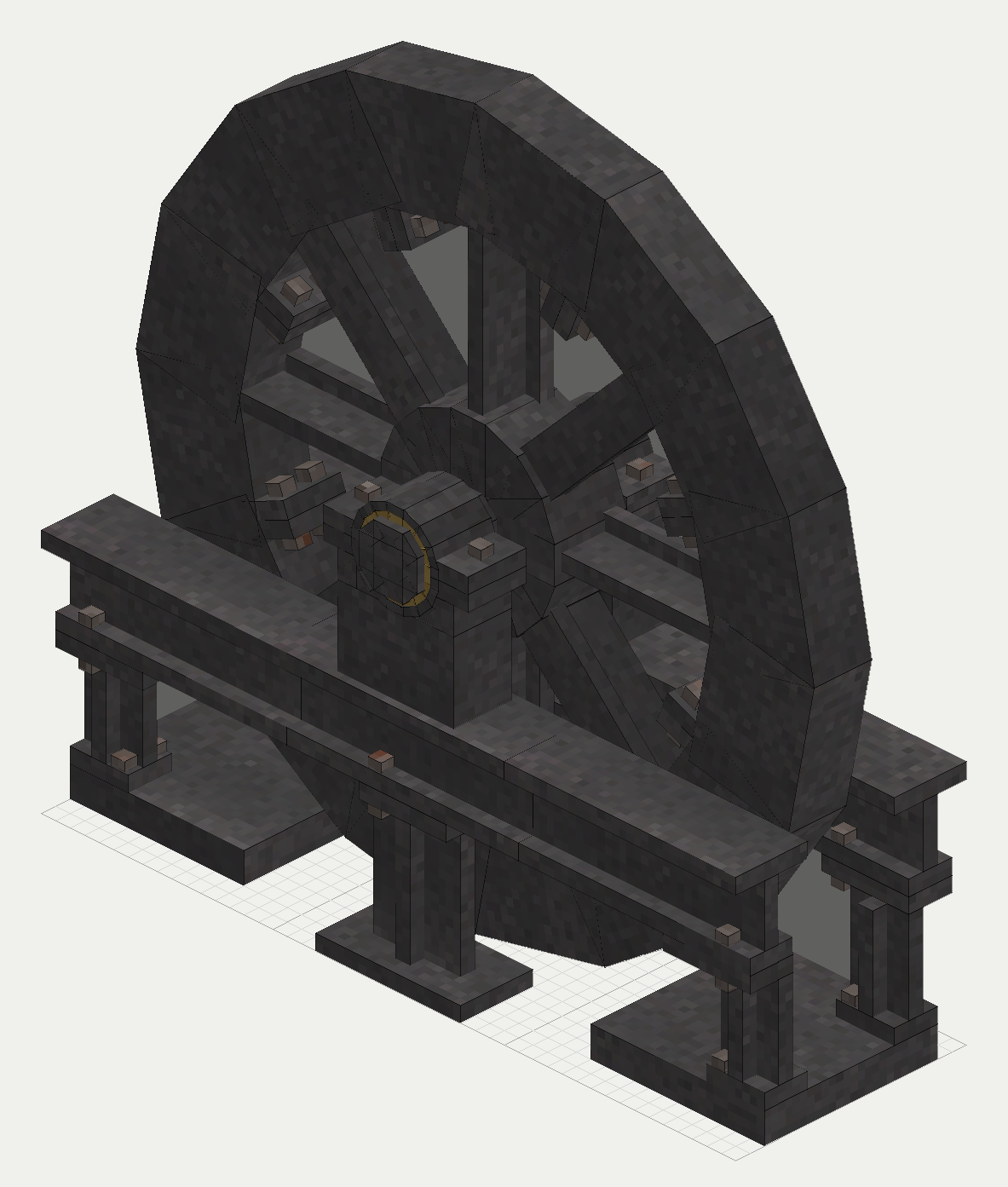
Fairbairn says it was "upwards of twenty years since" the fly-wheel became a first motion: teeth were cast on its rim and a pinion took the power straight off, which did away with the cumbrous gearing that had stood inside the mill (Fairbairn Mills II p. 100). Fairbairn's table of them runs from 12 to 300 horse-power and from 8 ft 11.5 in to 30 ft 1.5 in across (Fairbairn Mills II p. 101).
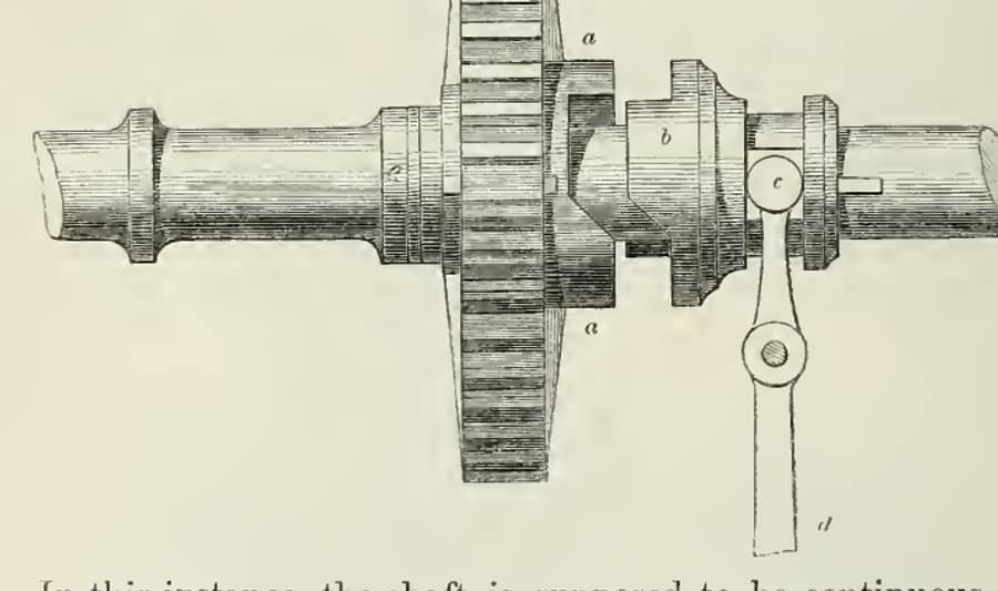
A works also needed to stop one thing without stopping everything. A form with sloped claws let a driven line overrun: the oblique faces fall out of contact and slide free when the driven side gets ahead, as where a water wheel and a steam engine share one line (Fairbairn Mills II pp. 88-89). Clutches between the upright and each room's shafting had been tried and were given up as "unsteady in practice" (Fairbairn Mills II p. 82).
Period basis, and what is the game's own
- Period: main and vertical shafts cast, line shafts wrought and faster (Fairbairn Mills II pp. 51, 72). The game plans the same two sizes, a cast main and a wrought line, and today has one cast shaft.
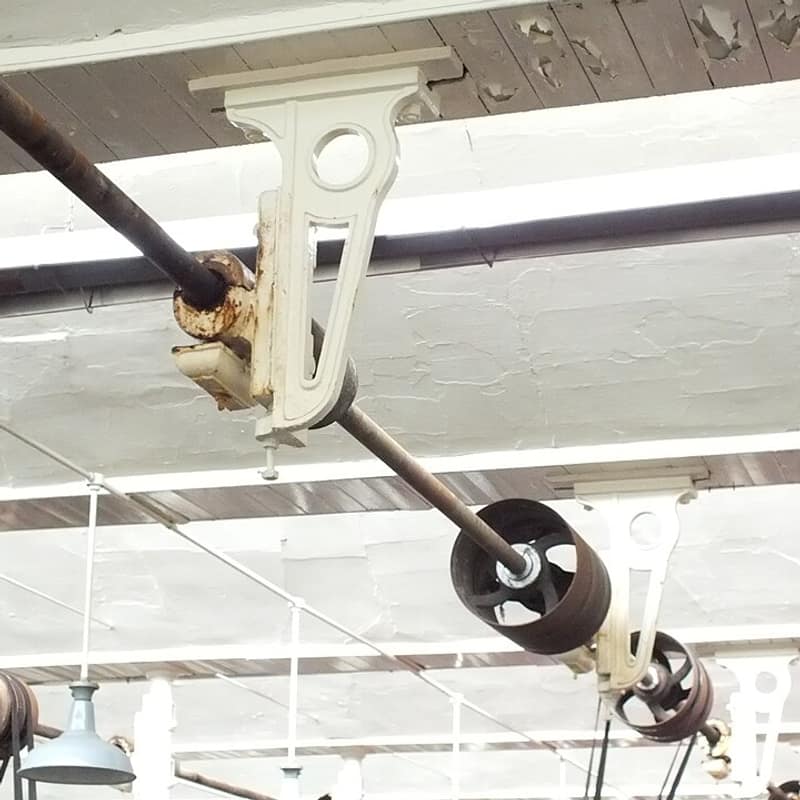
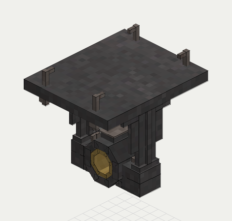
- Period: the line carried by floor pedestals, ceiling hangers and wall boxes, each a brass step in a cast seat, with a half-lap coupling at the joint beside the bearing (Fairbairn Mills II pp. 81, 93-98). The game plans these drawn at the supports it requires, and draws a half-lap at each joint.
- Period: a standing load that grew with the line (Fairbairn Mills II p. 72). The game plans a standing torque per shaft length and today charges one figure per run.
- Period: the bevel, spur and clutch hardware above. The game has the bevel, a two-to-one and a four-to-one gearbox with 2% lost at each geared station, and a clutch that joins two runs one to one; the disengaging coupling is built after Fig. 223, with a weighted lever, and its claws overrun.
- The game's own: the flywheel stores only and carries no teeth, and it stays on the shaft with no separate pinion off its rim.
- The game's own: no vanilla axle drives this shafting. Vanilla mechanical power is a speed with no storage and no turning force of its own; see vanilla against reality. The prime mover is the iron breast wheel, and a steam engine later.
- The game's own: the shaft does not need oiling today, and a dry Monday costs nothing. Bearings carry an oil factor in the planned model, held at one until there is an oil to change it.
The numbers
Shafting keeps period figures at true size (scale and units, how we scale). "Planned" is the design value; values without that word are what the game has now.
| In the game | Period figure | How it was scaled | Game value |
|---|---|---|---|
| Line shaft diameter | Table 8 sizes wrought shafting for 1 to 150 hp at 10 to 1000 rpm (Fairbairn Mills II p. 71) | Whole voxels at true size | Planned 125 mm (4.92 in), 2 voxels |
| Main shaft diameter | Saltaire 10 in vertical (Fairbairn Mills II p. 102) | Whole voxels at true size | Planned 250 mm (9.84 in), 4 voxels; today's cast shaft is this section |
| Line torque rating | Wrought shafting, d^3 = 250 H/R (Fairbairn Mills II p. 70) | The rule at face value | Planned 3.4 kN m working |
| Main torque rating | Buchanan's rule for fly-wheel shafts, d^3 = 400 H/R (Fairbairn Mills II p. 70) | The rule at face value | Planned 17.0 kN m working |
| Line power at rating, 19 rpm | Same | Torque x speed | Planned 6.8 kW, 9 hp |
| Main power at rating, 19 rpm | Same | Torque x speed | Planned 34 kW, 46 hp |
| Speed guide | 94 rpm Saltaire vertical, near 200 rpm spinning lines (Fairbairn Mills II pp. 102-105) | Not enforced | Planned 19 to 150 rpm line, 10 to 95 rpm main |
| Journal length | 1.5 diameters cast, 1.75 wrought (Fairbairn Mills II p. 73) | The rule at true size | Planned 1.5 d main, 1.75 d line |
| Coupling | Lap one diameter, box two (Fairbairn Mills II p. 81) | Whole voxels, box to 2.4 d across for the key | Planned, drawn at each joint |
| Span between supports | Deflection under 1/1200 of length (Fairbairn Mills II p. 60) | Whole blocks; a span is the game's own choice | Planned 3 m line, 4 m main |
| Standing torque | Grows with line length (Fairbairn Mills II p. 72); no figure given | The game's own | Planned 4.3 N m a metre line, 32.5 N m main; today one figure per run |
| Gear ratio | About 1.9 and 3.5 (Fairbairn Mills II pp. 123, 127-128) | Whole ratios | 2:1 and 4:1 gearboxes, 2% lost per station |
| Bevel teeth rating | Tredgold's rule, 400 lb per inch of breadth (Fairbairn Mills II pp. 43-44) | Applied to the drawn wheel | Planned 4.1 kN m |
| Flywheel across | 8 ft 11.5 in to 30 ft 1.5 in (Fairbairn Mills II p. 101) | Fits the block grid; much smaller than period | About 3 m and 5 m |
| Flywheel inertia | None given | The game's own, a disc's I scaling as R^4 x thickness | 10,000 and 150,000 kg m2 on the game's physical scale |
Open, and what you can tell us
Fairbairn's table gives fly-wheels by power and speed, but none of the books at hand says how a mill chose the mass of the rim for the job it did. If you know a period rule for sizing a fly-wheel against a rolling or forging load, we would like to read it.
Picture credits
- Line shaft: Jet Lowe, Historic American Engineering Record, public domain, cropped.
- QSMM Line shaft brackets 3212: Clem Rutter, Rochester, Kent, CC BY 3.0, cropped.
- Fig. 242, labelled for this page; Figs. 213, 230, 238, 239 and 223: Fairbairn, Treatise on Mills and Millwork, pt. II, pp. 103, 81, 94, 97, 98 and 88, Library page.
- The game's line hanger, bevel and flywheel: the mod's planned drawings.
Comment or suggest something in the Expanded thread on the Vintage Story Discord