
Watt beam engine
A Watt engine is a cylinder that works on steam and a cold vessel set apart from it, joined by a beam that rocks over a stone wall or an iron column. How to build and run one in the game is in the steam engines guide, and its parts are in the catalogue. This page is about the real one and how the game's follows it.
The problem it solved
Newcomen's engine made its vacuum by spraying cold water into the working cylinder. The vacuum was good and the waste was enormous, because the same iron then had to be heated again to take the next stroke of steam. Watt named the loss himself: the fuel it took to bring "the whole cylinder, piston, and adjacent parts from the coldness of water to the heat of steam, no fewer than from 15 to 20 times in a minute" (Thurston History p. 88).
His answer was to make the two jobs happen in two places. The patent of 1769 says that the cylinder "must, during the whole time that the engine is at work, be kept as hot as the steam", and that the steam "is to be condensed in vessels distinct from the steam-vessel or cylinder" (Thurston History pp. 99-100). Everything else on the machine follows from that split.
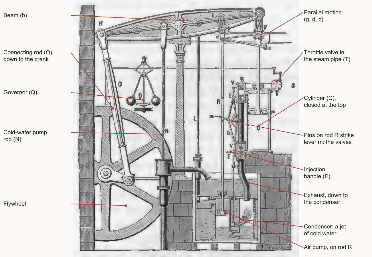
A separate cold vessel brings its own needs. Water and air gather in it and spoil the vacuum, so it needs a pump to clear them: the air pump, "wrought by the engines themselves" as the patent has it (Thurston History pp. 90, 100). Once the cylinder must stay hot, cold air can no longer follow the piston down, so Watt closed the top with a cover and let the rod slide through a stuffing box, wrapped the cylinder in a steam jacket, and greased the piston with oil and tallow instead of a layer of water (Thurston History p. 90).
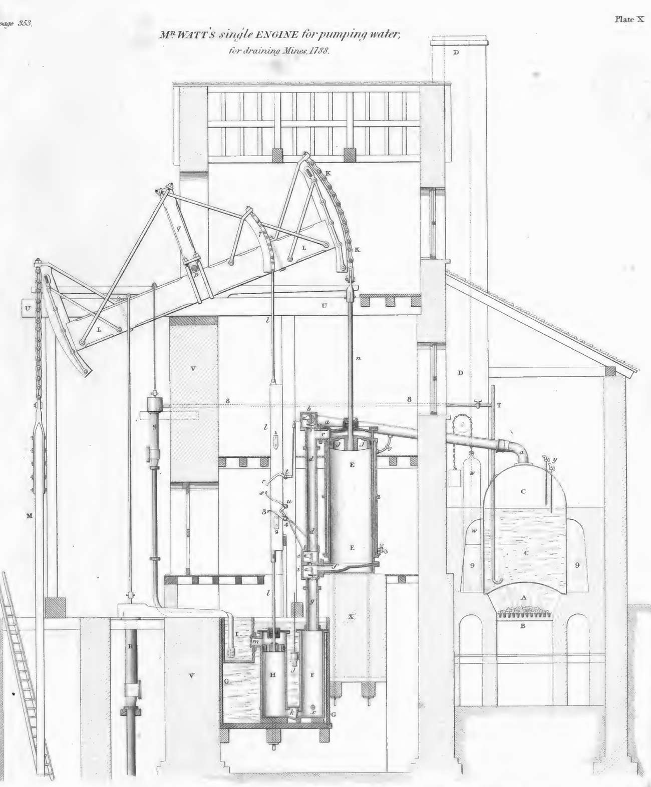
The first engines were single-acting. Steam pressed the piston down, an equilibrium valve then let the steam pass under the piston, and the weight of the pump rods at the far end of the beam drew it back up (Thurston History p. 99, Farey p. 354). For draining a mine that is all that is needed, and a chain is good enough, because a chain only ever has to pull.
Turning a shaft
Mills wanted rotation. Watt knew the crank from the common lathe, and made a model of two cylinders on one axis, but did not patent it. By Watt's own account a workman passed the idea to people around a rival's engine, and James Pickard took out a patent on the crank in 1780 (Farey pp. 409, 423-424). Without troubling to dispute it, Watt "contrived other means of effecting the same object" (Farey p. 424), and the one his firm built was the sun and planet.
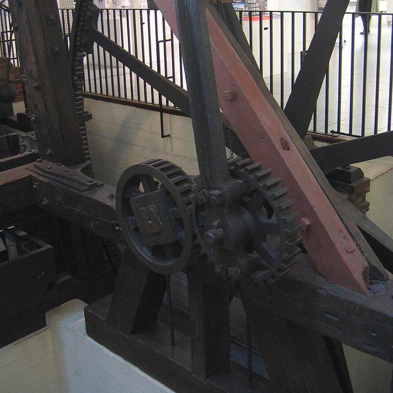
To turn a shaft evenly the engine had to push on both strokes, so steam was let in above and below the piston by turns, four valves now doing the work in pairs (Thurston History pp. 118-119, Farey p. 451). A chain cannot push. Thurston calls the sectors and chains or racks used until then a device whose "rudeness of design" was "only equalled by its insecurity" (Thurston History p. 112).
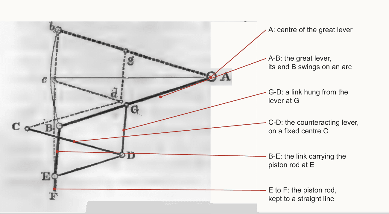
A linkage works through pins alone, pushing and pulling. Of the inventions in the specification of 1784, Farey names only the parallel motion and the locomotive engine as having come into extensive use (Farey p. 434).
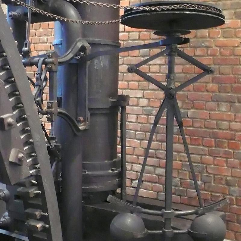
With power going to machinery the speed mattered, and a load could change at any moment. The throttle valve, a disc in the steam pipe turned edge-on or across, set the steam by hand or by the governor (Thurston History pp. 114-115, Farey p. 458). Fig. 31 shows the governor's rod going to it at T.
How it was kept and counted
Starting was a procedure, not a switch. The fire was raised, air was blown out of the cylinder and condenser with steam through a blow valve, and the engine waited until the injection and a barometer showed a vacuum forming; only then, with the flywheel turned by hand about an eighth of a turn, was the injection opened and the valves set going (Farey pp. 459-460). The condition of the condenser was read on a barometer gauge, a glass tube in mercury joined to the condenser, near 30 inches at perfect vacuum (Thurston History p. 117).
Boulton and Watt were paid in part out of what their engines saved, usually a third of the value of the fuel, which meant an honest tally of strokes was a business matter (Thurston History p. 114). Watt's answer was a counter on the beam, a train of dials moved by a pendulum as the beam rocked, locked and opened once a year (Thurston History p. 114).
Very little pressure was used. An engine well loaded had a mean exhaustion of about 9 lb a square inch below the atmosphere during the stroke, and the boiler stood only a few pounds above it (Farey pp. 486-487). Most of the work was done by the atmosphere on one side of the piston and the condenser on the other. Where a later engine has a thicker boiler, this one has a cold vessel. The ratings page follows what that meant for horse-power and coal.
Period basis, and what is the game's own
- Period: the separate condenser and air pump, and a jet of cold water to make the vacuum (Thurston History pp. 88-90). The game's planned drawing has them, and the injection cock is planned as a handle with five marks, from shut to fully open.
- Period: the barometer gauge and a stroke counter on the beam (Thurston History pp. 114, 117; Farey pp. 377-378, 520-521). Both are planned on the game's engine.
- Period: the parallel motion and sun and planet (Thurston History p. 105, Farey pp. 431, 450). The game's planned drawing carries the parallel motion, and the generator is planetary, the shaft turning twice for each double stroke.
- The game's own: there is no throttle or governor. The steam is set at the pressure valve in the line, and a shut injection is the planned way to stop the work.
- The game's own: the engine drives one attached sub-machine, a generator, a feed pump or a blowing engine, where a real engine drove whatever was geared or rodded to it.
- The game's own: today it runs from 2 to 4 atm through a plain on-off gate, a long way above Watt's pressures, and draws the same steam throughout. The planned rating removes the gate and takes the pressure down to Watt's.
- The game's own: pairing this engine with a Cornish boiler is a compression of the period. Boilers of Watt's time were wagon boilers (Fairbairn Useful p. 299); see the Cornish boiler page.
- The game's own: wear and a burst cylinder from over-pressure, after 60 s over the band, is the game's rule, with a wrench and parts to mend it.
The numbers
Engines keep period figures rather than the fuel factor of the iron furnaces (see the scaling page), at the drawn size (scale and units). "Planned" is the rating in design; the last rows are the game today. The ratings page sets it against the other engines.
| In the game | Period figure | How it was scaled | Game value |
|---|---|---|---|
| Bore | 30 in, a makers' "30 horse" (Farey p. 575) | The cylinder as drawn | Planned 750 mm (29.5 in) |
| Stroke | The stroke of a 10 horse (Farey p. 575) | The drawing | Planned 1.26 m (4.14 ft) |
| Speed | 17.5 double strokes a minute (Fairbairn Mills II p. 101) | Period figure; the sun and planet doubles it at the shaft (Farey p. 450) | Planned 17.5 double strokes, 35 rpm |
| Nominal power | d^2 v / 6050, at 6.944 lb a sq in (Farey p. 575) | The rule on the drawn size | Planned 20.9 hp |
| Mean pressure, full working | 12.7 lb a sq in, the vacuum included (Farey p. 486) | The rule on the drawn size | Planned 87.6 kPa, 28.5 kW indicated |
| Friction | 2 lb a sq in (Farey p. 486) | Period figure | Planned 13.8 kPa, the engine's standing torque |
| Useful power | Half as much more than nominal (Farey pp. 486, 576) | 10.7 lb a sq in over the area and speed | Planned 24.0 kW, 32.2 hp |
| Working pressure | 2 lb in the cylinder, 4 to 4 1/2 lb at the boiler (Farey pp. 486-487, 576) | Period figure | Planned 2 psi; nothing more above it |
| Break pressure | Above 12 lb, the wagon boiler (Fairbairn Useful p. 299) | Period figure | Planned 0.82 atm |
| Steam | 33 cu ft a minute a nominal hp (Farey p. 439) | Volume per stroke at 2 lb gauge | Planned 0.214 kg/s, 772 kg/h |
| Injection water | 22 to 23 lb a lb of steam (Rankine pp. 391-392); 0.6 cu ft a minute a nominal hp (Farey pp. 593-594) | Period figures | Planned 4.8 to 6.5 kg/s |
| Runs at | None; the gate is the game's own | Game value | Today 2.0 atm and above |
| Breaks above | None; the game's own | Game value | Today 4.0 atm, after 60 s |
| Steam and power | None; the game's own | Game values | Today 30 L/s for 0.3 of power |
Picture credits
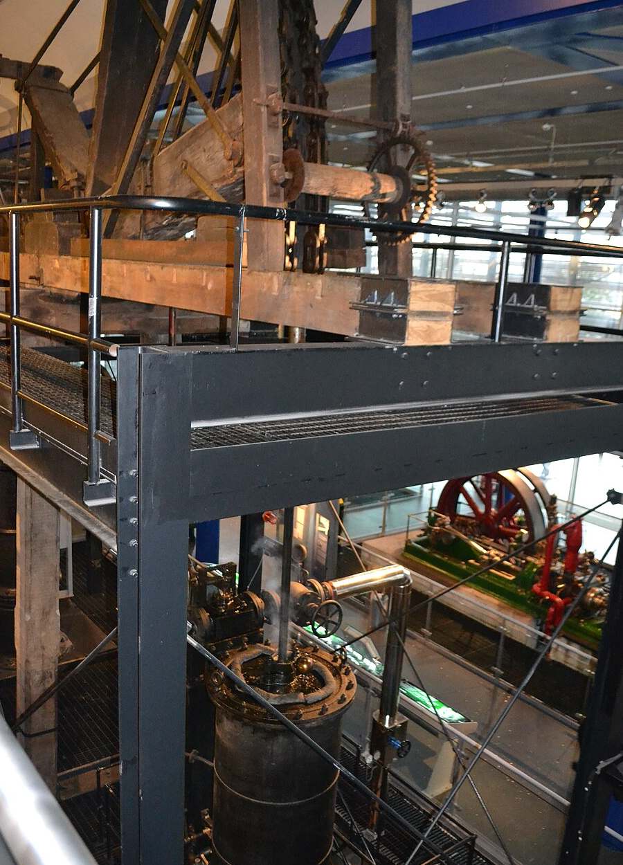
- Smethwick Engine at ThinkTank Museum: IMechE1, CC BY-SA 3.0, cropped.
- Boulton and Watt centrifugal governor: Dr. Mirko Junge, CC BY 3.0, cropped.
- Boulton and Watt sun and planet gear: Andy Dingley, CC BY-SA 3.0, cropped.
- Plate X, given on the plate as page 353, and the woodcut on Farey p. 431: A Treatise on the Steam Engine, Library page. The woodcut is labelled for this page.
- Fig. 31: Thurston, A History of the Growth of the Steam-Engine, p. 119, Library page. Labelled for this page.
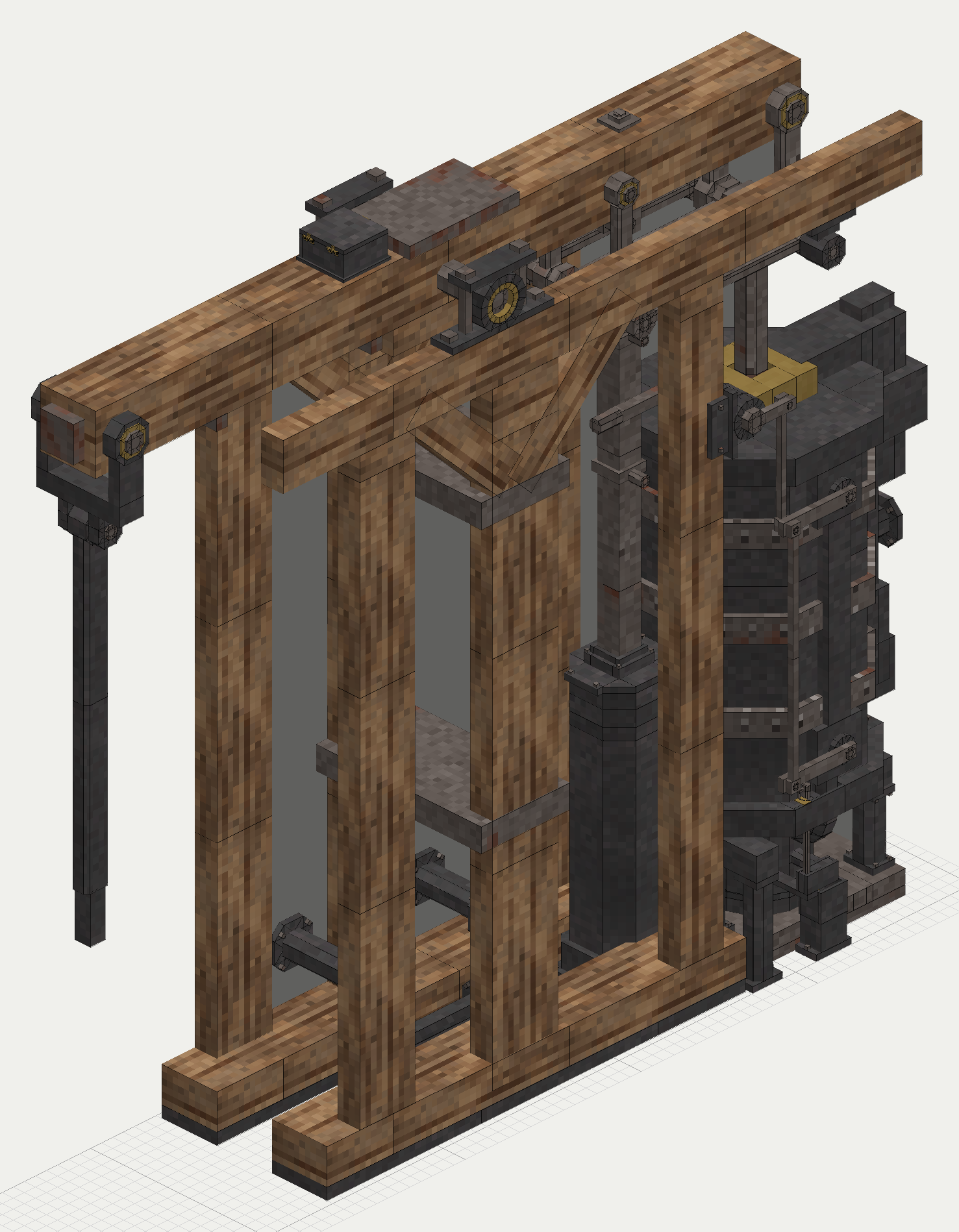
- The game's engine: the mod's planned drawing.
Comment or suggest something in the Expanded thread on the Vintage Story Discord