
Water wheels
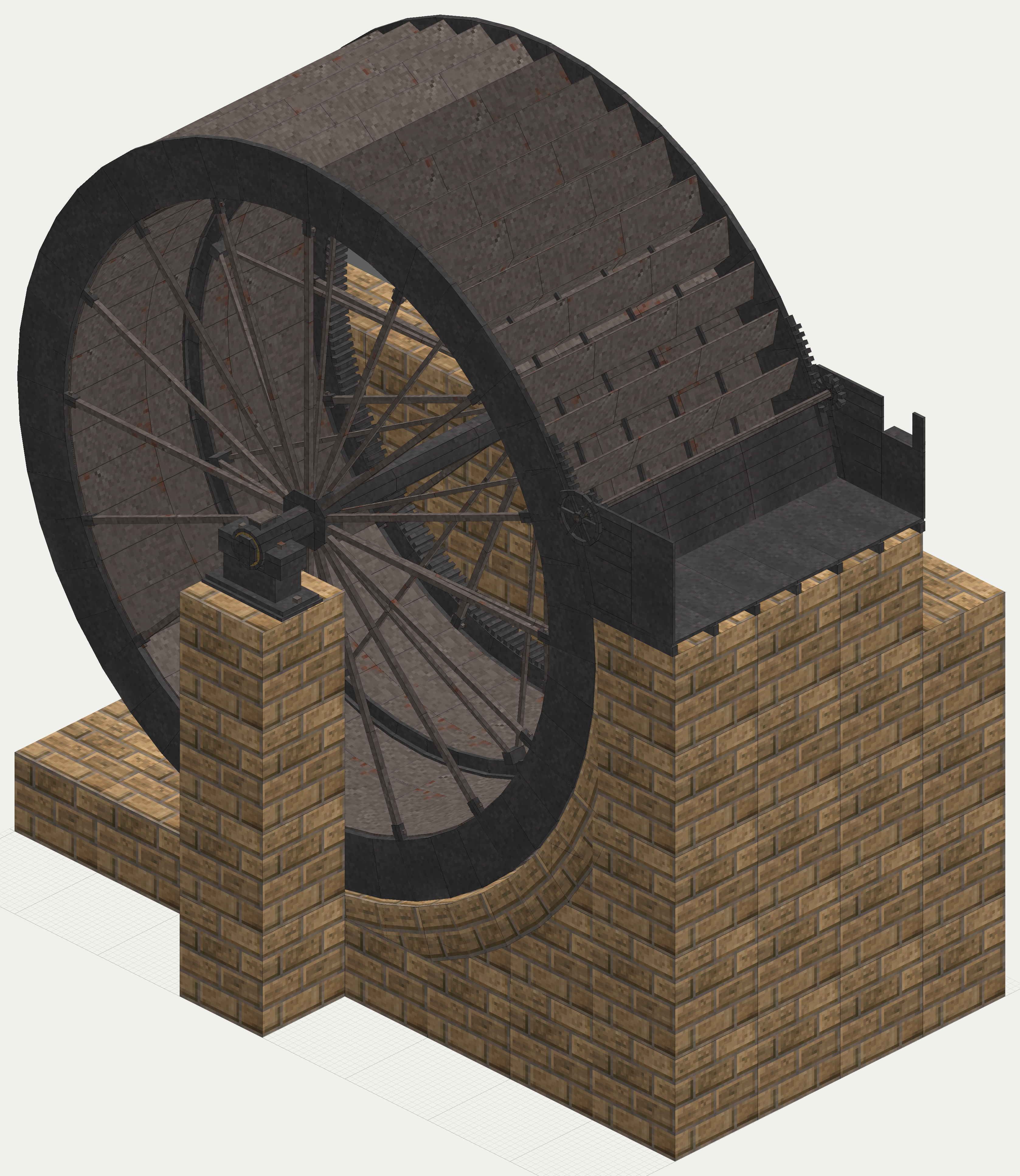
A mill's water wheel lowers water from the head race to the tail race and takes the work out on the way down. The iron breast wheel is the form that machine had reached by the middle of the nineteenth century, and the game's first prime mover for iron shafting. How its shaft network behaves in the game is in the shaft power guide. This page is about the real wheel, why it ended up in iron with the water laid on at the side, and how the game's follows it.
How the real one worked, and why it was built so
Before iron, undershot wheels were frequently employed, with straight floats struck by water rushing under a shuttle. This "was the invariable practice down to Smeaton's time even", the principle being to use the impulse of the stream and not its weight (Fairbairn Mills I p. 151).
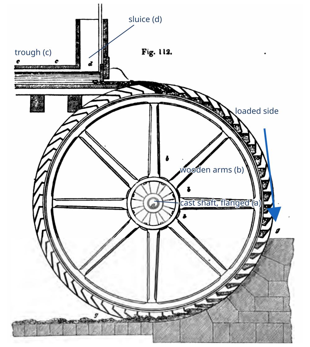
An overshot wheel works the other way, by weight. The stream is led over the summit, and the water retained in the buckets "continuously depresses the loaded side of the wheel" (Fairbairn Mills I p. 124).
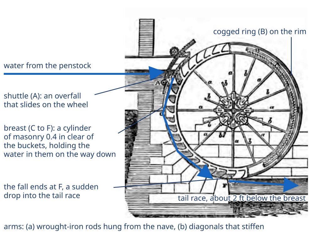
By Fairbairn's day "the breast wheel has taken precedence of the overshot wheel" (Fairbairn Mills I p. 116). Water laid on below the crest, at about 30 degrees from the vertical, needs a far cheaper pentrough than one carried over the top. A mill drew its reservoir down three or four feet in the day and refilled it overnight; a breast wheel takes the water at whatever height it stands, while an overshot wheel cannot work a falling supply without loss of power (Fairbairn Mills I p. 116). The name was already slipping by then, and "high-breast is perhaps a more correct designation" for most wheels called overshot (Fairbairn Mills I p. 125).
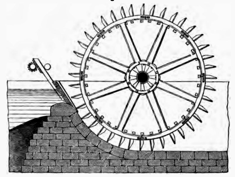
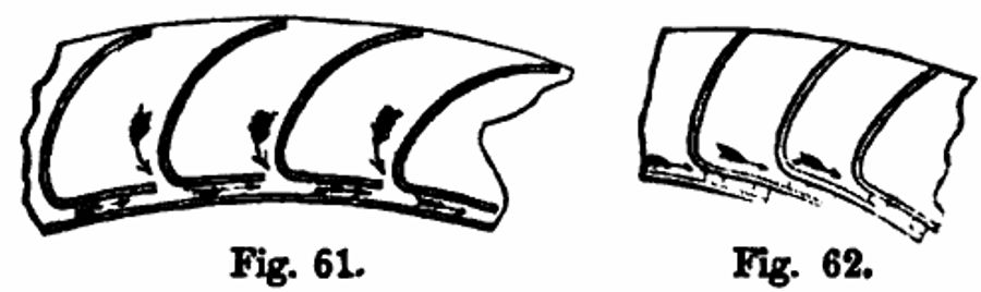
The breast itself is a curved trough of masonry, close to the wheel, which keeps water from spilling out of buckets as they tilt: "little or no space" between it and the wheel (Fairbairn Mills I p. 139), about 0.4 in in Rankine's description (Rankine p. 179). It is what makes the difference between the two names (Rankine p. 177). The tail race is sunk two to two and a half feet beneath the wheel, so the buckets can clear (Fairbairn Mills I p. 128), since a wheel standing in its own back water loses about a quarter of its efficiency (Rankine p. 176).
Efficiency was only half of why mills turned to iron. The other half was how much one wheel had to do. Some mills had first had a separate wheel for every machine; "one large water-wheel" with the machines around it concentrated the power, led to the factory building, and needed shafting (Fairbairn Mills II p. 50). Three changes made the large iron wheel work.
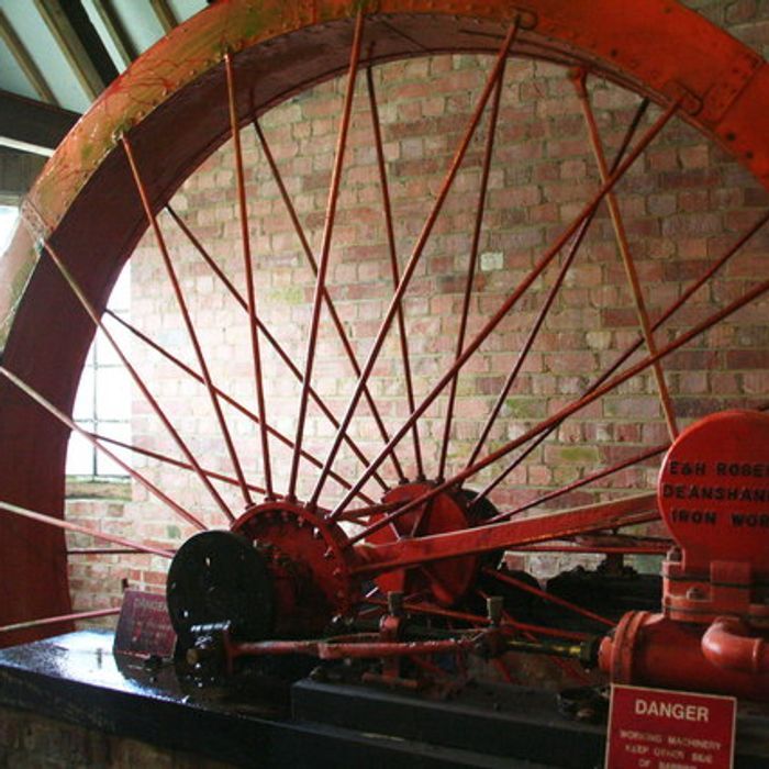
The first was to hang the wheel. Instead of stiff arms that act as columns, T. C. Hewes of Manchester supported the rim from the axle by thin rods of wrought iron, from a suggestion of William Strutt (Fairbairn Mills I p. 120, Fairbairn Useful p. 229). Arms were 2 to 2.5 in across on almost all wheels (Fairbairn Mills I p. 122). The rods only pull, those pointing down at the moment carrying the weight, and Rankine says the change "has greatly diminished the weight, cost, and friction of large water wheels" (Rankine p. 178).
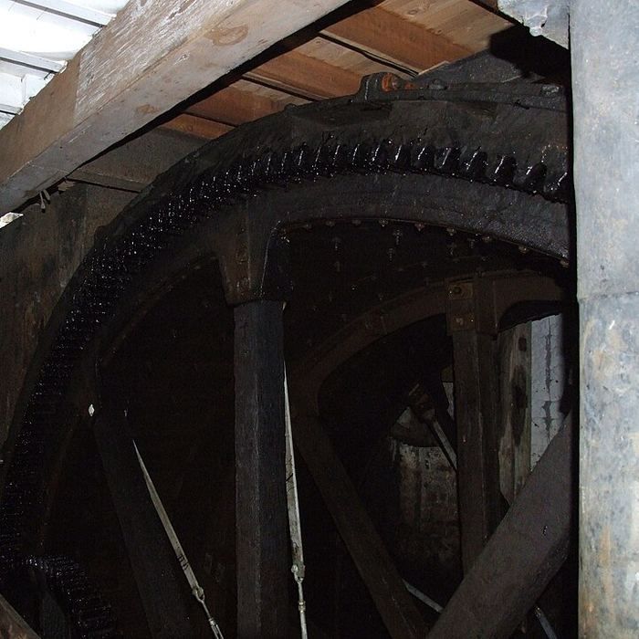
The second was to take the power off at the rim. Driven from the axle, the wheel's whole torque goes through the arms and shaft. With a toothed ring cast on the shroud meshing a pinion, "the arms, braces, and axle have only to sustain the weight of the wheel" (Fairbairn Mills I p. 141). The pinion must sit on the loaded side, below the end of the horizontal diameter, or a wheel hung on two-inch rods "would twist round upon the axle" (Fairbairn Mills I p. 140). Rim gearing also raises the speed at once: Catrine's ring of 48 ft 6 in drove a pinion of 5 ft 6 in (Fairbairn Mills I p. 132).
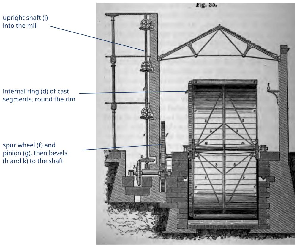
The third was to let the air out. Water falling into a closed iron bucket traps its air, and in flood a wheel at Linwood in 1828 threw spray six to eight feet above the entry. Vent openings cut in the sole gave "an increase of power of nearly one-third" (Fairbairn Mills I p. 136). The first wheel built for it was at Wilmslow the same year (Fairbairn Mills I p. 137).
How the water was held and the wheel kept to speed
A wheel was not started by opening the sluice wide. The shuttle was a closely fitting cast-iron arc with a door that slides, so "a thin sheet of water" flows over its upper edge (Fairbairn Mills I p. 143), and its motion "should in every case be slow", or the water surges and the wheel runs "first faster and then slower" (Fairbairn Mills I p. 147). A ball governor could work the shuttle (Fairbairn Mills I pp. 143-147), and on the Cleator wheel it raised and lowered it (Fairbairn Mills I p. 140). Buckets ran a third to a half full (Fairbairn Mills I p. 147), never more than two-thirds on the average supply (Fairbairn Mills I pp. 126-127), and Fairbairn kept the rim between 4 and 6 ft/s (Fairbairn Mills I p. 141).
All of this tied a mill to its stream. Catrine's two wheels of 50 ft ran on 48 ft of fall with "auxiliary steam-power" kept for dry seasons (Fairbairn Mills I p. 130). By the time Fairbairn wrote "nineteen-twentieths" of the mills were driven by steam (Fairbairn Useful p. 229), and it was the engine, not a better wheel, that freed mills from the site (Fairbairn Mills II p. 51). In the game the wheel gives way to steam the same way, through the Cornish boiler.
Period basis, and what is the game's own
- Period: the wheel is laid on at the side, on a fall of a half to three-quarters of its diameter (Fairbairn Mills I p. 140). The game's wheels take water at the axle on the normal and a row higher on the large, 0.6 and 0.71 of the diameter.
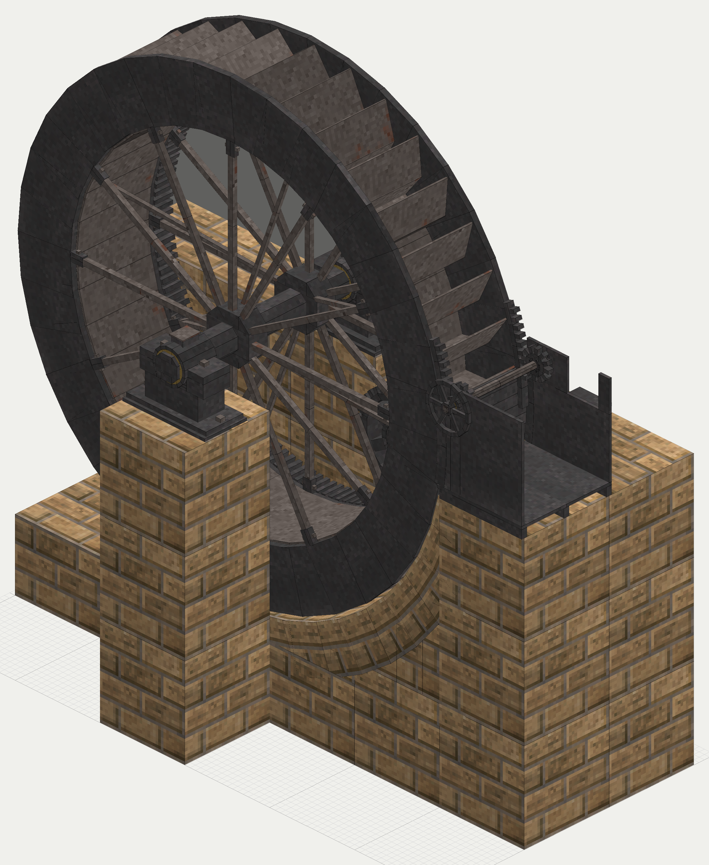
- Period: a cast axle on plummer blocks bolted to the masonry, segmented cast shrouds, wrought sole and buckets, thin wrought arms, a pentrough with a shuttle, a tail race, and the power off the rim (Fairbairn Mills I pp. 116-124, 141-143). The game draws all of these, and builds them from castings, plate and bar in stages.
- Period: the pinion on the loaded side below the end of the diameter (Fairbairn Mills I p. 140). The game's pinion sits there.
- Period: a wheel in a rising tail water loses power (Rankine p. 176), and the race has to be kept open (Fairbairn Mills I p. 128). The game keeps only the extreme of this: a tail race with its mouth blocked floods the pit and the wheel takes no water. The partial case is not modelled.
- Period: the governor on the shuttle (Fairbairn Mills I pp. 143-147). The game has no governor, because a stream that never runs short would give it nothing to save. The shuttle is the player's job, in quarter turns of the handwheel, and the slow opening is kept: on three streams the large wheel has to be brought up on half the sluice or its starting torque passes what the cast main can carry.
- The game's own: water is counted in whole streams. A stream is vanilla's rapid water, a rivulet running from a single spring, and a spring shared by several wheels gives each its share. There is no flood, drought, mill pond or back water, so a wheel's output depends only on the streams and the fall.
- The game's own: the torque curve. The books do not give a curve of wheel speed against load. The game holds power constant around the rated speed, doubles the torque at a stall because a slowed wheel can at most fill its buckets to twice their working level, and lets it run out at twice the rated speed, where the rim passes the water. The two-to-one comes from the fill rule above; the shape is the game's.
- The game's own: the base game's wheel gives a speed with no storage, and it needs rapid water at its paddles. See vanilla against reality. The iron wheel keeps that water source, and adds a fall built by the player, shaft torque, and a coupling that goes iron to iron with no timber axle in the line, as the iron shafting will not run off a wooden one.
The numbers
These are period ratios and formulas applied at the real wheel's size (the scaling page, scale and units). Every power and speed figure is a planned rating; each planned value is marked. The wheel's size follows from the blocks, and the water from one stream.
| In the game | Period figure | How it was scaled | Game value |
|---|---|---|---|
| Diameter | Fixed from the fall (Fairbairn Mills I p. 147) | Whole blocks at true size | 5 m (16 ft 5 in); large 7 m (23 ft) |
| Fall | Half to three-fourths of the diameter (Fairbairn Mills I p. 140) | Whole blocks | 3 m; large 5 m |
| One stream of water | 2,150 cu ft a minute at the start at Catrine, about 1,015 L/s (Fairbairn Mills I p. 131) | A rivulet a block wide, 0.3 m deep at 0.8 m/s, about a quarter of Catrine's | Planned 250 L/s |
| Water's power | 1 hp for 8.88 cu ft/s falling 1 ft (Fairbairn Mills I p. 113), the same as weight times fall | Applied as it stands | Planned 7.36 kW normal; large 12.3 kW on one stream, 36.8 kW on three |
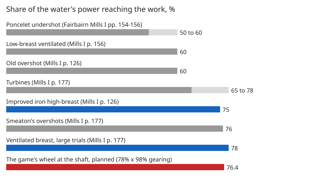
| Efficiency | 75%, iron high-breast (Fairbairn Mills I p. 126); "nearly 78" ventilated, large trials (Fairbairn Mills I p. 177) | The trial value, 0.98 taken off for the rim gear | Planned 76.4% |
| Power at the shaft | Catrine pair, 240 hp from a 48 ft fall (Fairbairn Mills I pp. 129-130) | Water power x efficiency | Planned 5.62 kW (7.5 hp); large 9.37 kW on one stream, 28.1 kW (37.7 hp) on three |
| Rim speed | 4 to 6 ft/s (Fairbairn Mills I p. 141) | Taken as a design speed | Planned 1.4 m/s (4.6 ft/s) |
| Bucket filling | A third to a half (Fairbairn Mills I p. 147) | Width and depth chosen to suit one stream | About 0.34 full at rated speed, planned |
| Buckets | 40 to 60 on a 20 ft wheel (Fairbairn Mills I p. 142) | Counted from the drawing | 36; large 48, planned |
| Shroud depth | 22 in on Cleator's 20 ft wheel (Fairbairn Mills I p. 140) | Taken from the book for the large; the normal's is the game's own drawing | 25 in; large 22 in, planned |
| Rim gear ratio | 8.8 : 1 at Catrine, 48 ft 6 in to 5 ft 6 in (Fairbairn Mills I p. 132) | Teeth set by the drawing | 4 : 1; large 5.6 : 1, planned |
| Stall torque | Buckets at most two-thirds, working at a third (Fairbairn Mills I pp. 126-127, 147) | Twice the rated torque | Planned 5.02 kNm; large on three streams 25.1 kNm, so it starts on the half sluice |
| Rotating ironwork | 34 tons on a wheel 18 ft by 20 ft broad (Fairbairn Mills I p. 119) | Each part's drawn volume at iron's density | 18.8 t; large 47.8 t |
Open, and what you can tell us
Fairbairn gives no curve of a wheel's speed against its load. A heavy wheel held its speed to a governor, so what it would have done without one, slowed by a sudden load, is reconstructed in the game from how full its buckets could get. If you know a period trial that logged speed and torque, or a modern measurement of a preserved wheel, we would like to read it. The game also leaves back water short of a blocked race, and a frozen race in winter, as things not modelled; tell us if a real mill's account shows how often either stopped the work.
Picture credits
- Water Wheel by E and H Roberts, Deanshanger Iron Works: Chris, CC BY-SA 2.0, cropped.
- Water wheel, Helmshore: Clem Rutter, Rochester, Kent, CC BY 3.0, cropped.
- Fig. 60, and Figs. 61 and 62: Rankine, A Manual of the Steam Engine and Other Prime Movers, pp. 179 and 180, Library page. Fig. 60 labelled for this site.
- Figs. 112 and 123: Fairbairn, Treatise on Mills and Millwork, Part I, pp. 124 and 151, Library page. Fig. 112 labelled for this site.
- Fig. 35: Fairbairn, Useful Information for Engineers, p. 230, Library page. Labelled for this site.
- Share of the water's power: drawn for this page from Fairbairn Mills I pp. 126, 154-156 and 177.
- The game's wheels: the mod's planned drawings.
Comment or suggest something in the Expanded thread on the Vintage Story Discord