
Simple horizontal engine
A horizontal engine lays the cylinder on its side and joins the piston to the crank by one straight rod, with a single sliding valve to work the steam. How to build and run one in the game is in the steam engines guide, and its parts are in the catalogue. This page is about the real one and how the game's follows it.
Why the beam went
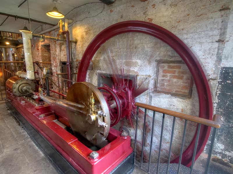
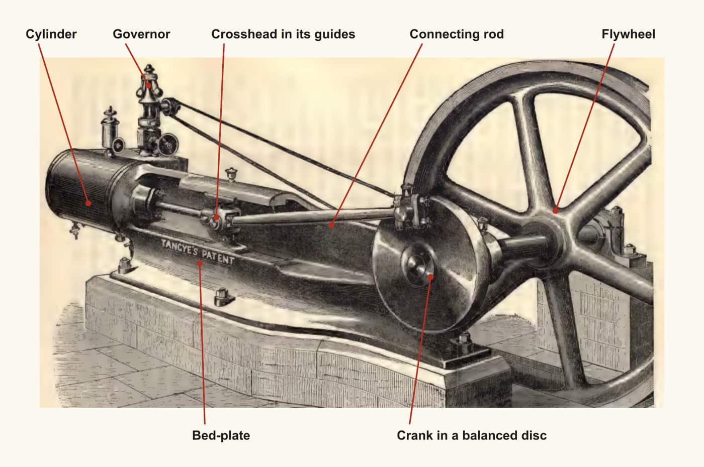
The Watt engine needs a beam because it began as a pump: a rocking lever over a wall, chains to the rods in the shaft. Put a crank on it and the beam stays as a heavy way of turning a push into a turn. Laying the cylinder flat removes it. The piston rod ends in a crosshead that slides in straight guides, the connecting rod runs from there to the crank pin, and nothing else stands between the steam and the shaft.
The reasons the period gave were about money and speed. Fairbairn, writing of iron works, says the horizontal non-condensing engine "from its compact form and convenience of handling, is admirably adapted for giving motion to the machinery of iron works", that it is "superior to the beam engine" there, and "much cheaper in its original cost"; and "all its parts being fixed upon a large bed plate", it "requires a comparatively small amount of masonry" (Fairbairn pt. II pp. 257-258). In 1870 an article on mill engines puts it the same way: less first cost, less expensive foundations and engine house, "a greatly higher speed" and, if properly built, "at least equally durable". It adds that "mill-owners had a strong prejudice against horizontal engines", now "rapidly dying out" (Van Nostrand p. 34).
By the end of the period the question was closed. "Where much power is required, the stationary engine is usually an horizontal direct-acting engine" (Thurston History p. 311). The modern mill engine, Thurston says in his manual, "is commonly a direct-acting, horizontal engine", at least for moderate and large powers (Thurston Manual p. 82). Horizontal direct action had also gone to sea early: the "Charlotte Dundas" of 1801-2 had a paddle wheel near the stern driven by "a direct acting horizontal engine, with a connecting rod and crank" (Rankine pp. xxiv-xxv).
The independent frame came from smaller work. Murdoch and Southern, meeting a demand for engines of 2 to 8 horse-power, began to build ones "all the parts of which are supported one by another", standing "quite independently of the building" (Farey p. 677). A bed plate is that idea made into one iron casting.
The slide valve
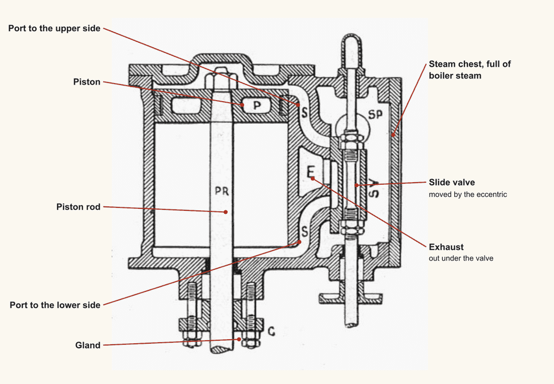
Watt's engine has four valves and the working gear to open them in pairs. The slide does it with one moving part driven by an eccentric on the shaft. Farey credits Murdoch's patent of 1799: the sliding valve "produces the distribution of the steam, to and from the cylinder, in a more simple manner than the four valves and working gear of Mr. Watt's original engine", and "is now universally adopted" (Farey p. 677). Thurston names the common three-ported slide "invented by Murdoch, while with Watt, about 1799" (Thurston Manual p. 41).
A plain slide opens and shuts the port at set moments. To stop the steam before the end of the stroke, so that it goes on pushing by its own expansion, the valve is made wider than the port: the "extension of the face is called lap or cover" (Bourne p. 184). Bourne gives the proportions: with an 18-inch valve stroke, 4 1/2 inches of lap on the steam side cuts the steam off with a quarter of the stroke still to go (Bourne p. 189). Boulton and Watt put enough lap on their valves to cut off at two-thirds of the stroke as the least expansion (Bourne p. 376).
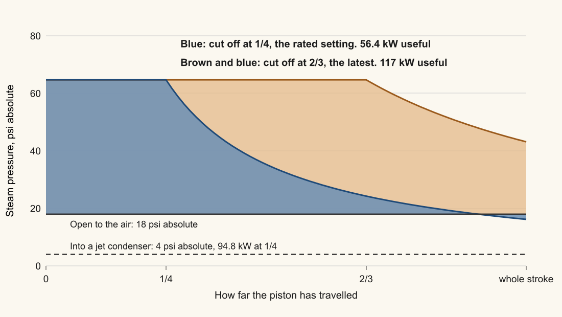
Expansion is why this matters. Steam stopped at half stroke does 1.7 times the work of the same steam let in for the whole stroke, at a quarter stroke 2.4 times (Bourne p. 183). A fixed lap, though, cannot follow the load, and what the governor does about that is the plain engine's weak point. On the small horizontal engine with a separate cut-off valve, Thurston counts it a disadvantage that setting the cut-off by the governor means "the heavy work which it throws upon the governor"; the best examples set the expansion valve by a screw and regulated through the throttle (Thurston History p. 311). Rankine prefers the other course, cutting off earlier rather than narrowing the opening and lowering the pressure by wire-drawing: "The former method makes the engine more economical, the latter less" (Rankine p. 417).
Where this engine stands against the Watt
The planned rule is the same arithmetic period engineers used: boiler pressure, Bourne's law of expansion, a real back pressure, a stroke at the piston speed Fairbairn gives. Lying down adds no efficiency by itself. The gain over the Watt comes from using the boiler's pressure and cutting the steam off early, and the design rates it at about 1.85 times the Watt's work for each kilogram of steam.
In the plan a single Cornish boiler open makes 0.264 kg/s, and the engine at its rated cut-off wants 0.267. It carries the engine to within 1% of full working, at 55.7 kW vented. Most of what sets this engine apart in play is that it starts without a condenser. A jet condenser on its exhaust is a choice the player can make later: it lifts the same engine to 94.8 kW.
Period basis, and what is the game's own
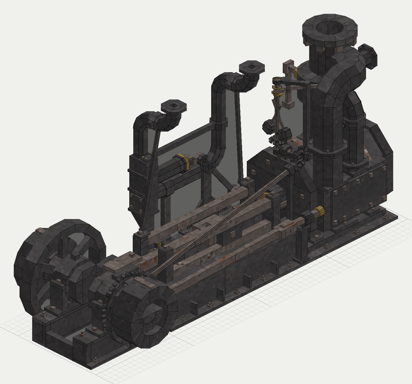
- Period: the horizontal direct-acting engine on a large iron bed, cylinder at one end and crank at the other, with a slide valve and a governor (Fairbairn pt. II p. 258, Thurston History p. 311). The game draws a cast bed, cylinder, valve chest with a slide valve, crosshead on bars, crank, flywheel and governor.
- Period: Fairbairn's iron-works engine is non-condensing (Fairbairn pt. II p. 257). The game plans it to run vented, and a condenser on the exhaust is optional.
- Period: the best small horizontal engines regulated through the throttle and set the expansion by hand (Thurston History p. 311), and a fixed lap gives a fixed cut-off (Bourne p. 189). The game plans the governor to set the cut-off between 1/4 and 2/3, and draws the governor working a throttle. A plain slide valve could not do that: the cut-off range is the game's own, for the sake of one rating rule.
- Period: cylinder condensation cost a good part of the steam, near 37% in one engine (Bourne p. 367). The game's own: the plan leaves it out.
- The game's own: today the block can be placed and shows its shape, but does not run, and it has no recipe. Every rating here is planned.
- The game's own: the base game has no steam engine. See vanilla against reality.
- The game's own: an overloaded engine labours and stalls and does not cut out, and a governor droop of 4% sets how fast it falls off above its rated speed.
The numbers
Engines keep period figures (see the scaling page), drawn at true size (scale and units). Every value below is planned: the engine does not run today. Fuller context for all the engines is on the ratings page.
| In the game | Period figure | How it was scaled | Game value |
|---|---|---|---|
| Piston speed | 300 ft a minute (Fairbairn pt. II p. 101) | The true value on the drawn 10-voxel stroke | Planned 73 rpm, 7.7 rad/s |
| Bore and stroke | 10 in by 20 in to 30 in bore (Thurston History pp. 311, 313) | Whole voxels at true size | Planned 0.625 m bore, 0.625 m stroke |
| Steam | 49 lb on Allen's engine (Bourne p. 356) | Round 50 psi, 3.4 atm gauge | Planned 50 psi; it breaks above 100 psi, the game's own limit |
| Cut-off | 1/4 gives 2.4 times the steam's work (Bourne p. 183) | Period rule, the rated setting | Planned rated 1/4, latest 2/3 |
| Back pressure | 18 psi absolute open, 4 psi condensing (Rankine p. 409) | True value | Planned the same |
| Friction | 12 to 15% of indicated power (Bourne p. 367) | 15% | Planned indicated 66.4 kW at 1/4 |
| Useful power, cut-off 1/4 vented | No test of this engine; the rule above | Mean pressure x piston x stroke x strokes, less friction | Planned 56.4 kW, 75.7 hp, 0.267 kg/s |
| Useful power, cut-off 1/4 condensing | Same | Same | Planned 94.8 kW |
| Useful power, cut-off 2/3 vented | Same | Same | Planned 117 kW, 0.712 kg/s |
| Torque | None given | Power over speed | Planned 7.3, 12.3 and 15.2 kN*m for the three settings above |
| Governor droop | None given | The game's own | Planned 4% |
Open, and what you can tell us
The books at hand do not say why mill-owners distrusted the horizontal cylinder, only that they did (Van Nostrand p. 34). They also do not name the first stationary horizontal engine or date its adoption. And they give two dates for the sliding valve: Thurston has Murdoch using "D-slide valves" on his oscillating engine of 1785 (Thurston History p. 133), and his manual and Farey both date the three-ported valve to 1799, Farey by its patent. If you know a source that says what the objection was, or who first built one for a mill, we would like to read it.
Picture credits
- Horizontal Steam Engine, Quarry Bank Mill: David Dixon, CC BY-SA 2.0.
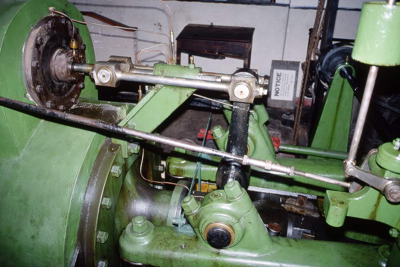
- Horizontal rolling mill engine (c1890), Blists Hill: Gillett's Crossing, CC BY 2.0.
- Slide-valve cylinder, section (Heat Engines, 1913): public domain, scanned by Andy Dingley; words added over the plate.
- Fig. 95: Thurston, A History of the Growth of the Steam-Engine, p. 312, Library page; turned upright, words added over the plate.
- The stroke diagram: drawn for this page from the game's planned figures and Bourne p. 183.
- The game's engine: the mod's planned drawing.
Comment or suggest something in the Expanded thread on the Vintage Story Discord