
Pumps
A boiler boils away its water and a condenser wants far more of it, so every steam plant is also a small waterworks. How to lay out the water in the game is in the steam and boilers guide, and the blocks are in the catalogue. This page is about how the real thing raised and pushed water, and how the game's follows it.
How water was really raised
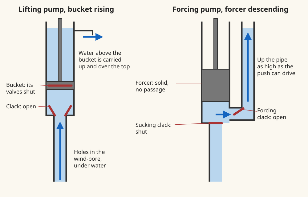
The old mine pump was the lifting kind. Farey calls them sucking-pumps: a column of iron pipes standing in the water, its lowest length, the wind-bore, pierced with small holes at the foot. A clack a few feet up had two leather-faced iron doors opening upward, and above it was the working barrel, bored true for a bucket with a leather edge and two valves of its own (Farey p. 154). The bucket drawn up shut its valves and carried everything above it; fresh water followed through the clack into the space it left. On the way down the bucket's valves opened and it sank through the water, so the bucket and the clack held the water up by turns (Farey p. 155).
The air does the first part of the work. Suction is only the atmosphere pushing water up into a space with less pressure, and it can do that to "any height less than 34 feet" (Farey p. 10). Below that a pump has to go down to the water. In a deep mine the shaft was divided into lifts, each pump raising the water into a cistern for the one above it, with fifty yards as "as great a depth as is proper for one lift" (Farey p. 155).
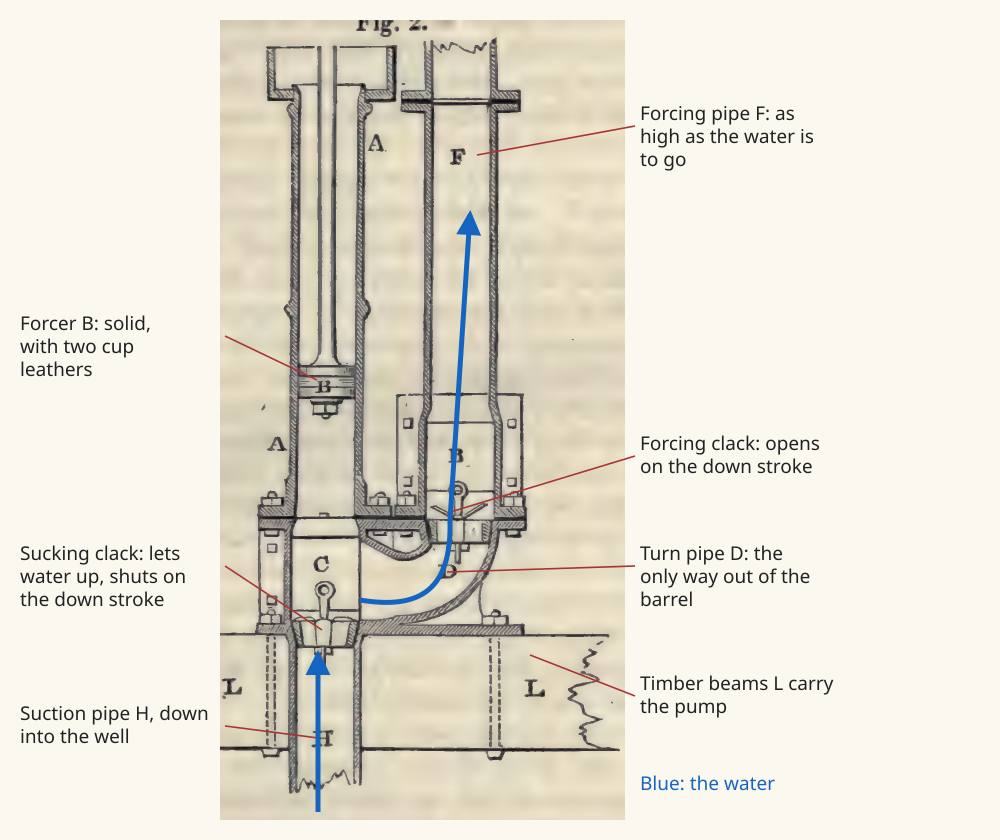
A forcing pump adds the second clack and takes the valves out of the piston. Farey's example was a water-works pump whose forcer, "surrounded by two cup leathers", was made so that no water could pass it (Farey p. 249). Everything in the barrel had to go out of the side, through the forcing clack, and it could not come back (Farey p. 250). The pump is fixed down to two strong beams with a hole left between them for the suction pipe, its weight and the whole water column taken on a flange at the bottom of the box (Farey p. 250).
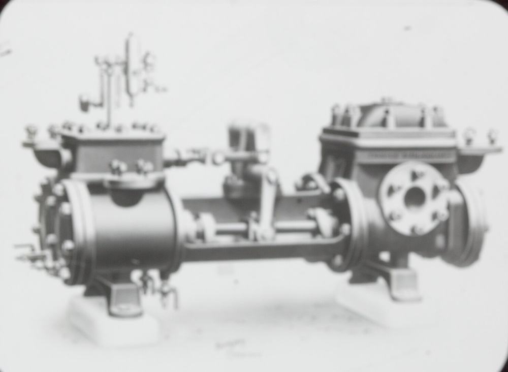
Pushing water through a long pipe by strokes is hard on pipe and engine alike, since the whole column has to start and stop. Boulton and Watt's pumping engine of Farey's chapter delivered into an air vessel 4 ft across and 9 1/2 ft high. The pump forced water in on its working stroke and squeezed the air above; on the return stroke, with the pump idle, the air drove the water out of the far side, so the stream kept moving "without any intermission" (Farey pp. 720-721). The game's planned feed pump keeps that pump and its air vessel.
Why a boiler needs a pump of its own
A boiler is a closed vessel pressing outward on everything, and the feed has to go in against that pressure. Early engines at low pressure could feed by gravity: a boiler could take its water from an elevated cistern through a pipe (Farey p. 122), or from the hot well, so long as the steam was not strong enough to hold the water back in the feed pipe (Farey p. 261). Stronger steam ended that. A boiler then wants a forcing pump, and to keep working it wants more of one than it strictly needs: "the feed pump should be capable of discharging twice the quantity of water that is consumed in the generation of steam", to cover leakage and priming (Bourne p. 225).
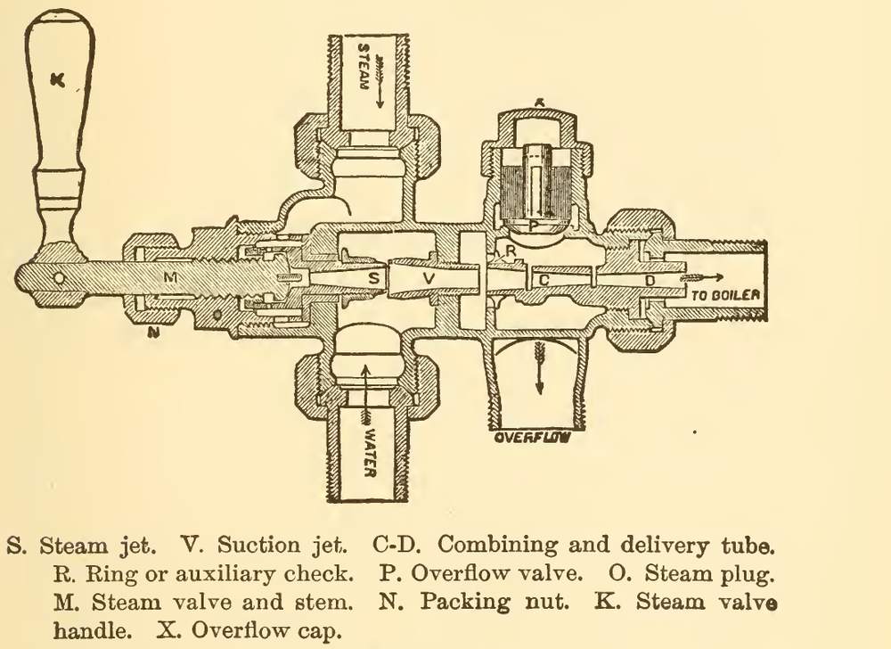
The injector did the same work with no moving parts, and looks like a trick. It is not: the steam leaves its nozzle very fast, about 1,700 ft a second at 60 lb, condenses in the water to a thousandth of its bulk, and keeps its speed, and that jet goes in against the boiler's own pressure (Hawkins p. 206). Hawkins spells the name of its inventor Gifford (Hawkins p. 206). He calls the injector "nearly perfect" as a thermodynamical machine, its heat going back into the boiler, though its mechanical efficiency is very low and it is "not an economical device, but it is simple and convenient" (Hawkins pp. 208, 211). He also says what it will not do: for high steam pressure it needs cold water (Hawkins p. 210). He would have every boiler with two feeds, one of them an injector (Hawkins p. 206).
How the game does it
The game divides the chain in two, and the division is its own. The fluid intake is a block that sits on open water and is the only place water enters a pipe. The pumps only move water from one line to another, and the intake refills what they take.
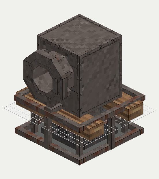
Four pumps feed a boiler, each paid for in a different way:
- The manual pump costs the player's own time, and works for a cold boiler. It is planned to weaken against pressure as a real one would.
- The mechanical pumps run from the line shaft or a waterwheel, wood first and cast iron later, for bulk water to a cold boiler or a tank (planned).
- The feed pump is an engine's module, running while the engine turns.
- The injector costs live steam and has no moving parts in its work (placed, its process not built).
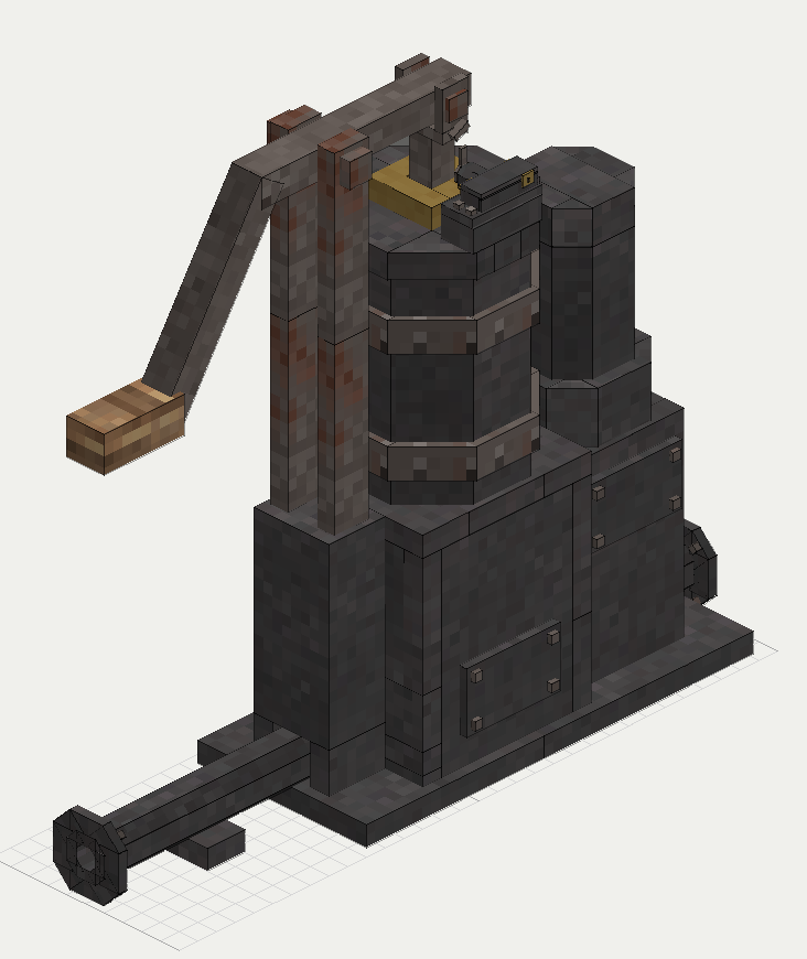
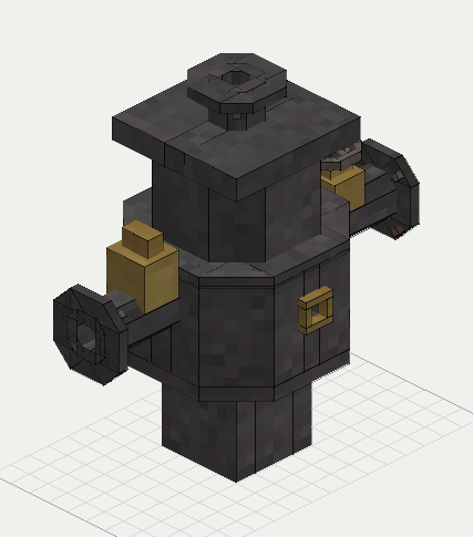
The feed tank is planned as a stack of cast-iron courses of flat flanged plates. A pipe holds very little, so without a tank the pump must run for as long as the boiler drinks. A tank lets it fill now and spend later, which is the job Farey's cisterns did between lifts (Farey p. 155). See also the Cornish boiler for what the water is going into.
Period basis, and what is the game's own
- Period: the parts and their order, suction pipe, clack, barrel, forcer or bucket with leathers, forcing clack, and a door to each clack (Farey pp. 154, 249-250). The game's planned drawings keep these.
- Period: the air vessel on the delivery, its branch in at the bottom and the delivery out of the far side (Farey pp. 720-721). The game plans it on the feed pump.
- Period: atmospheric suction has a limit (Farey p. 10). The game plans the same limit, at 10.2 blocks, with deeper water needing a pump at the water.
- Period: two feeds on a boiler, one an injector (Hawkins p. 206). The game gives four ways to feed and does not require two.
- Period: the injector needs cold water at high steam pressure (Hawkins p. 210). The game plans a limit of about 40 C on the water reaching an injector.
- The game's own: the intake makes water from a pond that never falls, and today wants a solid 3 by 3 by 3 of water under it. A lake's frozen skin does not stop it, but ice right under it does. Planned instead: a rate following the water it can reach, so a pond gives little and a river a lot.
- The game's own: the source side stands at a fixed 1 atm, in place of a real well's head.
- The game's own: today the feed pump delivers at 0.75 of the engine's inlet pressure, so a steam pump cannot beat the boiler driving it, and the boiler takes its feed without a pressure gate. Planned: the real arrangement, a large steam piston on a small water plunger, with pressure gained by their ratio and paid for in flow.
- The game's own: the feed tank's course sizes follow the plates, not any period cistern.
The numbers
Pumps are drawn at true size (scale and units); each row says whether its rate is a period figure or the game's own, and the scaling page covers how period figures are brought in. "Planned" is the rating in design; values without that word are what the game has now.
| In the game | Period figure | How it was scaled | Game value |
|---|---|---|---|
| Feed pump output | Cold-water pump 1/24 of the cylinder's capacity, a condensing engine's (Farey p. 592); feed pump twice the water boiled (Bourne p. 225) | Planned from Farey's 1/24, a rule for the condenser's supply. Today's rate is the game's own | 15 L/s on a Watt engine, 10 to 40 L/s on the Cornish engine; planned 13.6 L/s |
| Boiler's water use | Bourne's rule would make the pump twice this | Game's own | 4 L/s boiling; the boiler can draw 20 L/s to fill |
| Manual pump | A man at a pump, 13.2 lb at 2.5 ft a second, 10 hours a day: 33 ft lb a second, 44.7 W (Rankine 1876 p. 626) | Game value at 1 atm. Planned: a man's work against pressure, at about 50 W | 2 L/s; planned about 0.14 L/s at 3.6 atm |
| Suction lift | Any height less than 34 ft, 10.4 m (Farey p. 10) | Water's own limit | Planned 10.2 blocks |
| Lift per pump in a shaft | 50 yards "as great a depth as is proper for one lift" (Farey p. 155) | Not used | Not modelled |
| Delivery pressure | None given | Game's own | 0.75 of the engine's inlet; planned above the boiler, by the piston-to-plunger ratio |
| Feed tank | None given | Game's own, by the plates | Planned 560, 3,060 or 7,560 L a course; 30 L/s each side |
Open, and what you can tell us
Bourne gives the feed pump's size as a share of the water raised to steam, and Farey gives only the cold-water pump, the one that supplies the condenser. The books at hand do not give a size rule for the boiler feed of a land mill engine of Farey's time. If you know a source that sizes it, we would like to read it.
Picture credits
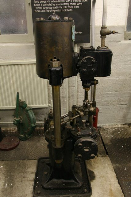
- Bradford Industrial Museum - boiler feed pump: Chris Allen, CC BY-SA 2.0.
- Tangyes Ltd, Horizontal Duplex Boiler Feed Pump, circa 1910: unknown author, public domain, cropped.
- Fig. 2: Farey, A Treatise on the Steam Engine, p. 249, Library page, labelled for this site.
- Fig. 101: Hawkins, Maxims and Instructions for the Boiler Room, p. 207, Library page.
- The two pumps: drawn for this site from Farey pp. 154-155 and 249-250.
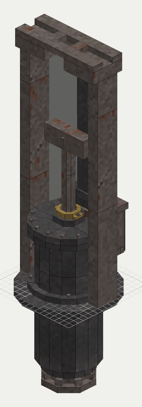
- The game's feed pump, intake, manual pump and injector: the mod's planned drawings.
Comment or suggest something in the Expanded thread on the Vintage Story Discord