
Cornish pumping engine
A Cornish engine is a beam engine without a crank or a flywheel. It stands over a mine shaft, lifts a long line of timber rods with one stroke of steam, and lets their weight do the pumping on the way down. Nothing like it is in the game yet: the engine for draining deep workings is planned, with no date on the roadmap, and so is the flooding it would answer. The engine of the name that ships in the later mod is a different machine, described at the end. For the engines the game has now see the steam engines guide and the Watt engine page.
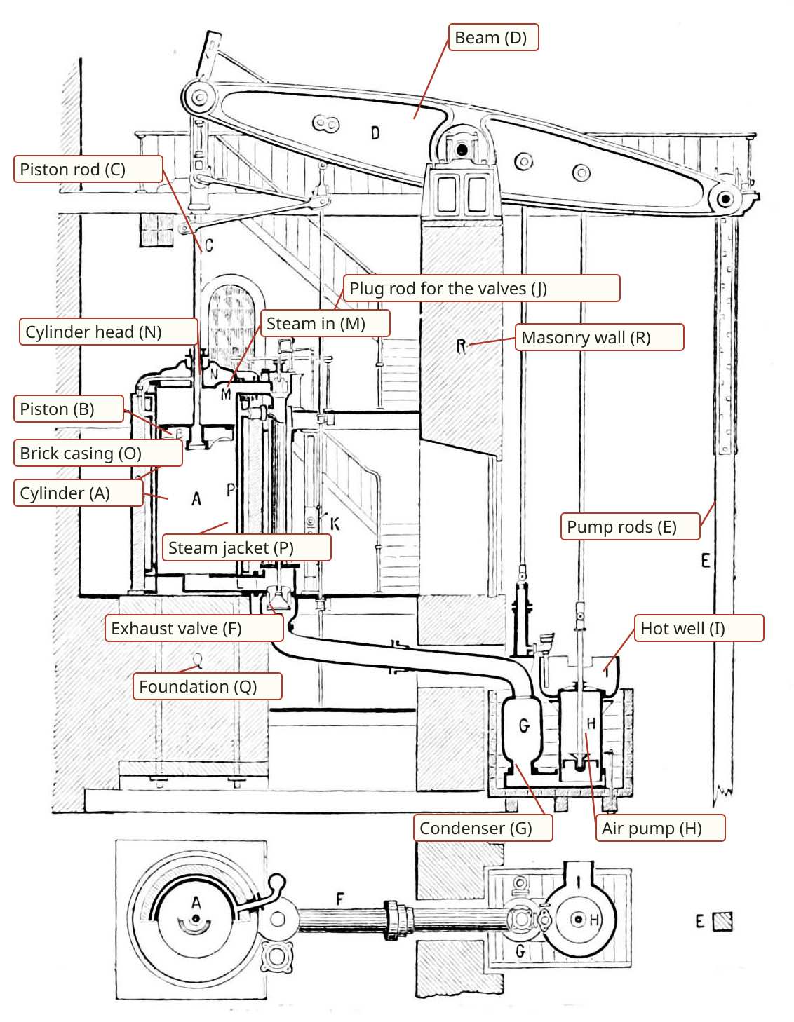
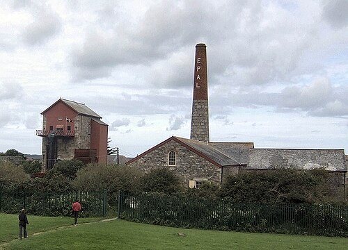
There is no drawing of the planned engine yet, so this page has no render of the game's own.
How the real one worked, and why it was built so
The engine exists because a mine goes below its own drain. Water falling on Cornwall, about 50 in a year (Hunt p. 621), sank into the workings, and an adit driven in from a valley could only carry off what lay above it (Hunt pp. 618, 620). Everything deeper had to be lifted to the adit. The Gwennap district's great adit ran nearly 30 miles (Hunt p. 618) and at a mean of 909 cu ft a minute the water pumped up into it came from 100 to 200 fathoms down (Hunt p. 620). Forty mines together pumped as much as 20,000 gallons a minute, most in spring and least in autumn (Lean pp. 141, 143).
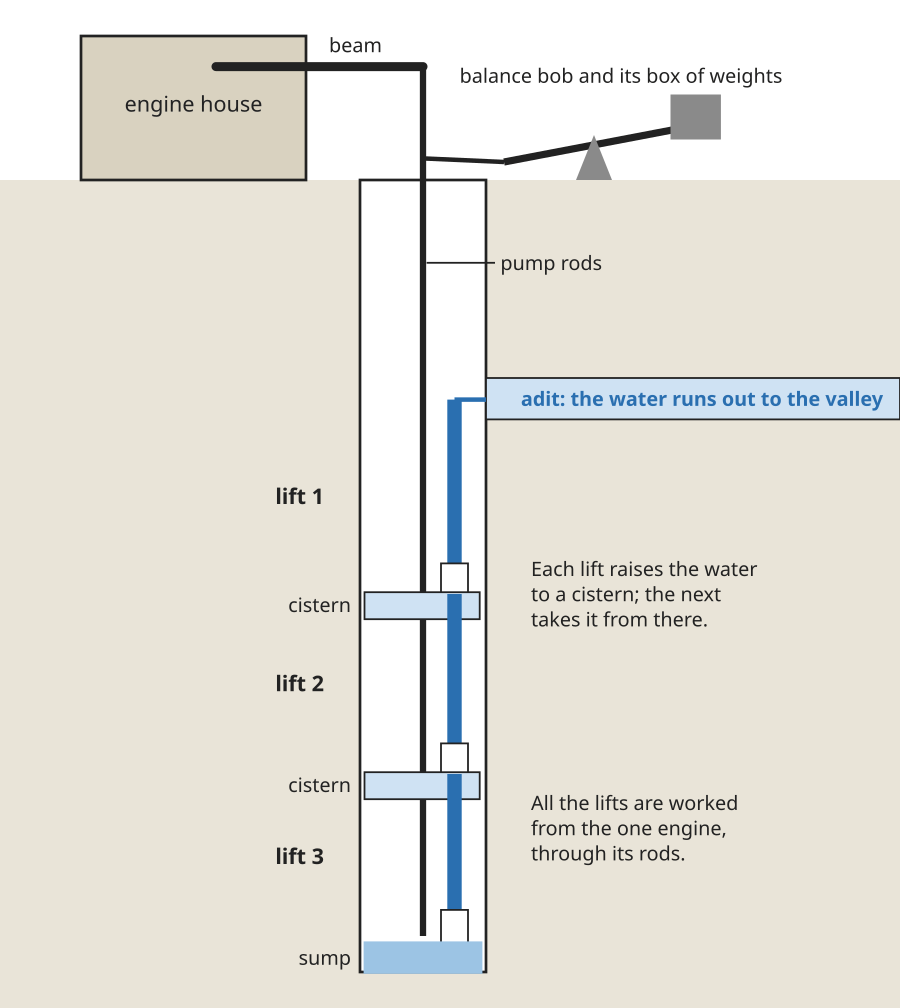
Pumping water out of a deep shaft is an odd load. It is enormous, it is always the same, and it needs lifting slowly in a straight line. The beam engine had no reason to turn anything, so the crank and flywheel of a mill engine were left off (Rankine p. 523). The stroke then has two halves that do quite different jobs.
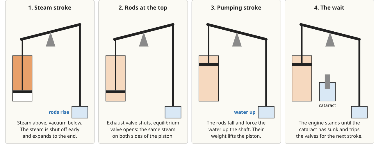
Two consequences follow. The rods must weigh a little more than the water and the friction, so the fall is sure: Rankine calls it "a slight preponderance" (Rankine p. 525), and Thurston says weights were added where the rods were too light and counterbalanced where too heavy (Thurston History p. 330). And with no crank to fix the stroke, its length depended on matching the steam to the load. An engine let run too far would strike the cylinder head, and buffer beams stood ready to stop it (Thurston History p. 330).
The cataract is what suited the engine to a mine. Its plunger is lifted by the engine, then sinks at a rate set by a cock worked by hand; when it reaches the bottom it releases a catch and the stroke begins (Thurston History p. 330). Smeaton's engine at Chacewater was set "so as to draw up exactly as much water as drains into the mine", and with little water it made four or five strokes a minute with long rests between (Farey p. 190). The engine's speed was set by the water, not by demand for power, and the engineer set it with one cock.
Why Cornwall built the best engines
Coal in Cornwall came by sea from Swansea (Farey p. 337), so an engine's appetite was a direct charge on the mine. Duty was the Cornish answer: the millions of pounds of water raised one foot by a bushel of coal, 94 lb in Lean's trials (Lean p. 3, Hunt p. 625). The water was taken from the capacity of the pumps rather than weighed (Lean p. 3), and a published monthly report began in 1811 for the proprietors who paid for it, which were "the test by which engineers must submit to be judged" (Lean pp. 3, 10). The engine ratings page has the whole curve.
Watt himself, of the engine at Herland and its 20 million in 1798, said that "The machine is perfect, and no further improvement can be expected" (Lean, under 1832). After 1800 Boulton and Watt's representatives left, and the engines fell off until the reports began (Lean p. 8). Then the figures climbed. Working steam expansively, with high pressure, and clothing the cylinder raised the fleet from about 20 million in 1814 to 47.8 in 1834 (Lean pp. 11-12 and under 1834). The best single engine, Austen's at Fowey Consols, did 125 million in a trial of 1834 (Lean, under 1834).
The method rested on a boiler that could be fired slowly, for "slow combustion is usually considered desirable, and boilers are usually made of large dimensions" (Hunt p. 642), and on high steam shut off early. At United Mines in 1838 steam at about 50 lb/in2 was shut off at a fifth or sixth of the stroke (Lean pp. iii-iv). See the Cornish boiler, which took its name from the same place and period. Hunt, writing in 1884, says no further gain had come for many years, and that none would until higher pressure was expanded further (Hunt p. 641).
Depth grew with the engines. A Newcomen engine reached 90 fathoms, Watt's about 200, and the high-pressure engines of 1812 to 1828 about 290 (Hunt p. 638). The plunger pole replaced the common pump piston at Crenver and Oatfield in 1801, because engines had been idle a third of their time for changes of leather (Lean p. 9).
What the game plans
The planned engine does this one job. It stands over a shaft and works a lift in the sump through rods, and it runs nothing else. Its cataract cock is set by hand, a stroke with no water in the sump spends its steam for nothing, and a stroke counter is planned to show it, in the way a mine captain read the engine. It is sized to hold the deepest band of the planned flooding, at the depth where a wet seam reaches 48 blocks under cover. The numbers are at the end of the page.
Period basis, and what is the game's own
- Period: single-acting, non-rotative, stroke set by a cataract (Rankine p. 523, Thurston History p. 330, Farey p. 190). The planned engine takes this form.
- Period: rods down the shaft to a pump at its foot, the lift split where a column would be too long (Hunt p. 622). The planned engine does this, with a new lift and cistern where the main passes its rating.
- Period: a rising main and a drain to an adit (Hunt p. 620). In the planned flooding the water stands no higher than the lowest opening to daylight, so an adit drains what lies above it.
- Period: for every fathom of depth the lodes drained five fathoms out at the surface (Hunt p. 622). The planned reach of a running lift is five blocks out for each block of depth.
- The game's own: the planned lift is a bucket lift, in which the steam stroke raises the water through the rods in tension. A plunger lift, the Cornish deep-mine form (Lean p. 9), needs rods heavier than the water, and at the game's 48 m the rods weigh about 4.4 t against 21 t of water, so it would need 18.4 t of weights hung on them, by the game's own arithmetic. The fall of the rods therefore does not do the pumping in the planned engine.
- The game's own: depths are a tenth of the period's, and the inflow of a working is a game choice, 1.4 to 6 times a real mine's.
- The game's own: the engine of this name that ships in the later mod is a stronger Watt, driving the same machines, with a control rod that sets its throttle. It is planned to retire when the deep-well engine is built. See the vanilla against reality page for how far the base game stands from all this.
The numbers
Cylinder, stroke and speed keep period figures (how we scale) at true size (scale and units). Everything marked planned is design, not built; the last row is what ships now.
| In the game | Period figure | How it was scaled | Game value |
|---|---|---|---|
| Cylinder | 60 in, Great Work (Lean Table IX, Hunt p. 625) | Whole voxels at true size | Planned 1.50 m bore (59 in) |
| Stroke | 9 ft in the cylinder, 7 ft in the pump, Great Work (Lean Table IX) | Whole voxels at true size | Planned 2.75 m and 2.125 m |
| Speed | 7.4 to 7.7 strokes a minute, Great Work (Hunt p. 625) | Kept | Planned 7.5 a minute at full working, less with the cataract |
| Steam | About 50 lb/in2, shut at 1/5 to 1/6, United Mines 1838 (Lean pp. iii-iv) | Kept | Planned 3.4 atm at the valve, cut-off 0.162 |
| Load on the piston | Friction with imperfect vacuum 3.5 lb/in2 (Hunt p. 639) | Added to the water load | Planned 13.2 psi of load, 16.7 psi indicated, 94 ihp |
| Water lifted | Dolcoath 16.0 L/s from 347 m, Wheal Darlington 68.9 L/s from 144 m (Lean Tables IV, V) | Depths a tenth, the game's own inflow | Planned 117.3 L/s from 48 m; the deepest band's design inflow is 93.9 L/s |
| Pump barrel | 13 5/8 in, Dolcoath; 14 in plunger, Consols (Lean p. 110, under 1827) | Follows from the water and shallower lift | Planned 0.75 m (29.5 in) |
| A single lift | 31 m at Chacewater, 55 m at Consols (Farey p. 191; Lean, under 1827) | The main's burst rating | Planned 37.2 m rough, 62.0 m faced |
| Boilers | Four at East Wheal Rose (Hunt p. 642) | The steam it draws | Planned two Cornish boilers |
| Duty | 64.4 million for 70 to 80 in in 1835, best 85 to 91 (Lean Table VII) | Follows from steam and boilers | Planned 72.4 million a 94 lb bushel |
| Beam | No Cornish engine's beam is weighed in the books; Chacewater's 4 t lever (Farey p. 175) | Scaled by the piston force, oak, trussed and strapped (Farey p. 355) | Planned about 6.5 t, 7.13 m |
| Engine of this name, today (later mod) | None | The game's own | 8, 16 or 32 L/s; runs from 5, 6 or 7 to 8 atm; 40 L for a unit of power |
Open, and what you can tell us
The books at hand do not give the size of a Cornish engine's beam, the weight of its rods or balance bobs, or the measurements of its house; Farey weighs only the atmospheric engine at Chacewater (Farey pp. 175-176). The book that would carry them, W. Pole's treatise on the Cornish pumping engine of 1844, could not be found in a free scan. The beam and house in the plan are therefore inferred. If you have a source for those sizes we would like to read it.
Picture credits
- The Cornish pumping engine, 1877: Popular Science Monthly, vol. 12, public domain; labels added.
- East Pool mine, Taylor's Shaft engine house: John M, CC BY-SA 2.0.
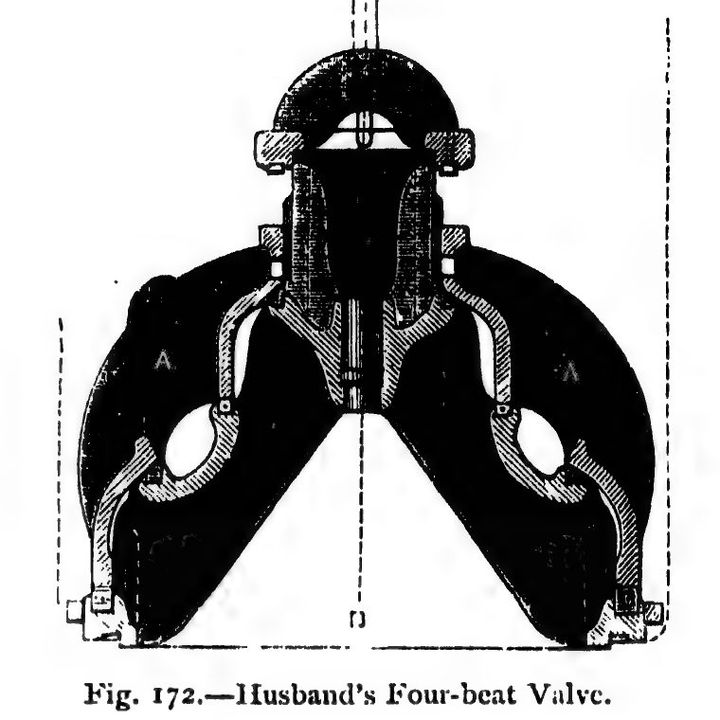
- Fig. 172, Husband's four-beat valve: Hunt, British Mining, p. 631, Library page.
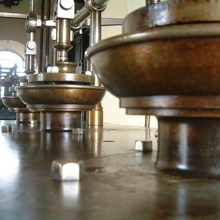
- 90 inch engine valves, Kew Bridge Steam Museum: Les Chatfield, CC BY 2.0, cropped.
- The shaft: drawn for this page from Hunt pp. 620, 622 and 634, Farey p. 191 and Lean.
- The stroke: drawn for this page from Hunt p. 639, Rankine p. 525 and Thurston History p. 330.
Comment or suggest something in the Expanded thread on the Vintage Story Discord