
Compound Corliss engine
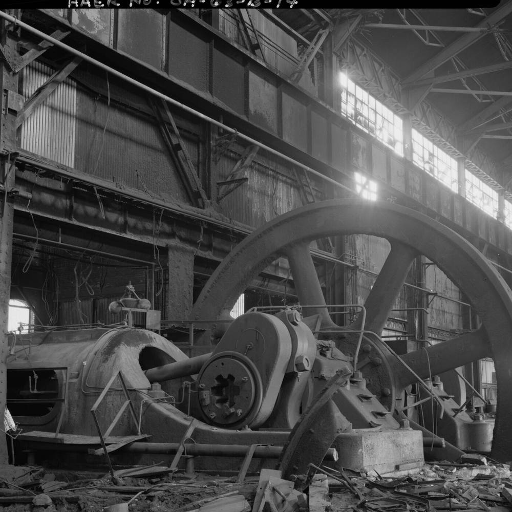
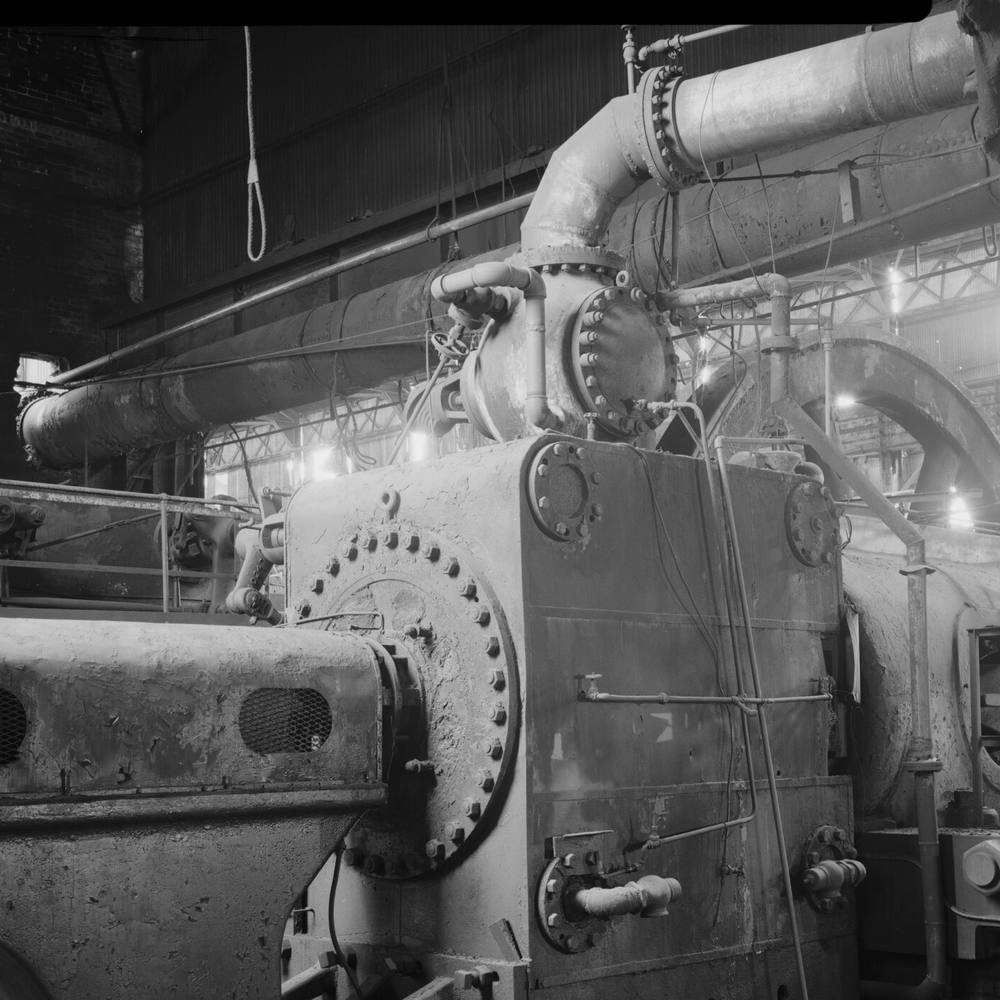
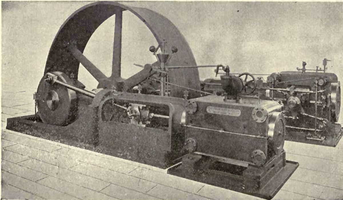
The Corliss engine is a horizontal mill engine with an unusual way of letting steam in: four small rocking valves, and a catch that lets go of the steam valve at a moment the governor picks. Compounding passes the same steam through a second, larger cylinder before it leaves. Thurston, listing what it brought together, records "a remarkable economy of fuel" (Thurston Manual p. 102). In the game this is the planned top of the power ladder, part of the later steel mod: it is sized and ruled, but it is not drawn or built, so this page has no render of it. For the engines before it see the horizontal engine and the engine ratings.
What the valve gear does
An engine's governor has to do something when the load changes. On the plain horizontal engine it closes a throttle (Thurston History p. 311), which wastes pressure before the steam has done any work. Corliss made the governor change how long the steam valve stays open, so the full boiler pressure always reaches the piston and the load only alters how far it expands. Thurston dates this governor-controlled cut-off to Corliss in 1849 (Thurston Manual p. 89).
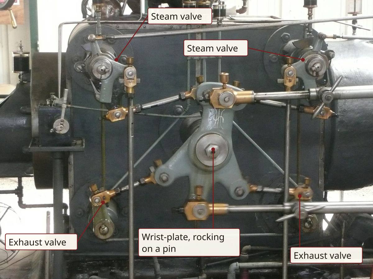
Thurston's list of what made the design new is the clearest statement of it (Thurston Manual pp. 100-102): four valves placed so as to reduce clearance to a minimum; a rotating valve, cheap to fit and worked from outside the steam spaces; one wrist-plate on one eccentric for all four; a detaching gear that drops the steam valve shut; the governor directly setting the expansion, with the least possible work thrown on the governor itself. The separate valves matter too: with a steam- and an exhaust-valve at each end of the cylinder, the steam passages are short and the clearance small, "a source of some economy" (Thurston Manual p. 97).
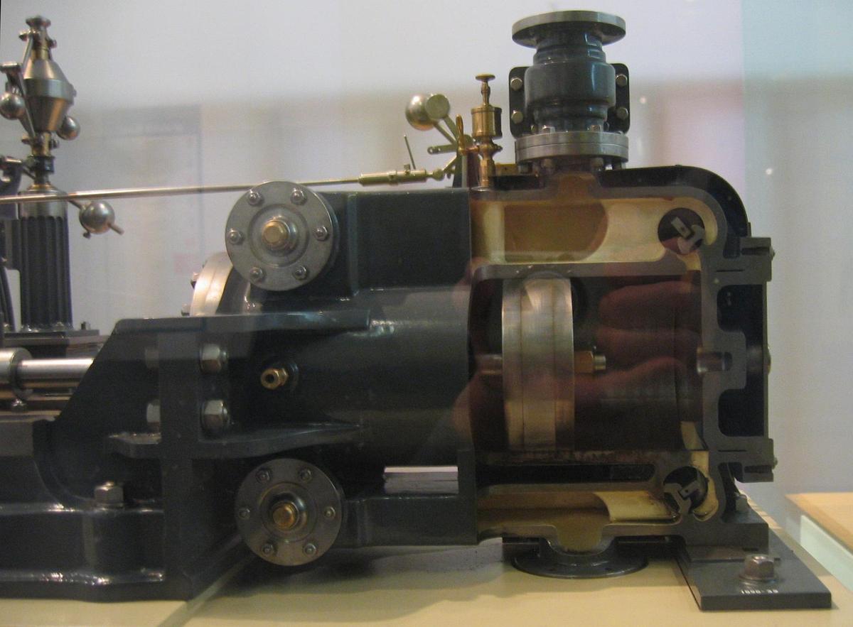
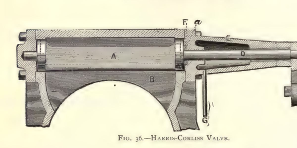
The valve, once tripped, is pulled shut by a spring or a weight, helped by a vacuum chamber, and would slam. The dash-pot takes the shock: a piston on the valve gear drops into a shallow cup and cushions on trapped air. Sickels had used water for the same purpose; Corliss used air (Thurston Manual pp. 99-100).
The trip has a limit that follows from the geometry. The catch can only let go while the eccentric is still opening the valve, which ends at about half stroke. Past that the valve closes at the eccentric's own slow pace, so a release was wanted before then (Henthorn pp. 19-20).
Why cutting the steam off early saves it
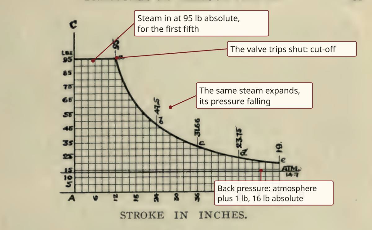
Tribe puts the result of the Corliss gear plainly: its expansion curve "approaches very closely to the Hyperbolic curve", the ideal one, and "at least twenty-five per cent. of the fuel can be saved as compared with the slide valve arrangement" (Tribe p. 50). Condensing takes it further: the same engine exhausting at 7 lb absolute rather than 16 gains about 40% on the non-expansive, non-condensing engine (Tribe p. 51). A jet condenser does that work on the back pressure.
Why a second cylinder
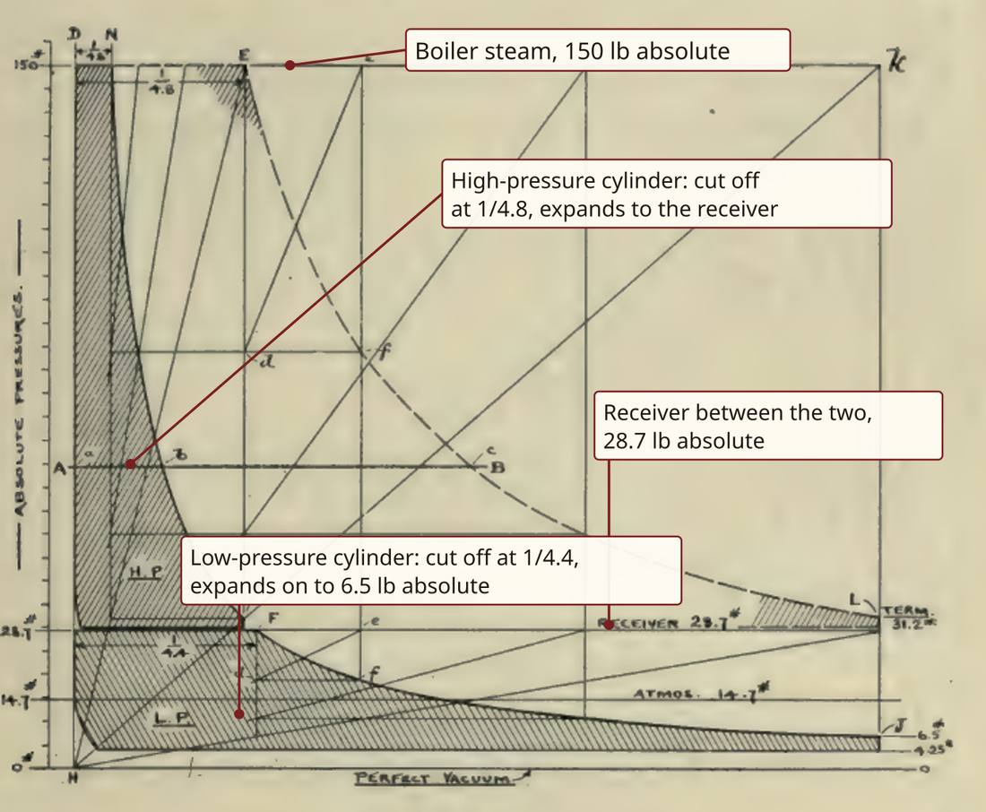
If expansion is so good, a long expansion in a single cylinder should be better still. What stops it is the iron. Steam falls in temperature as it expands, and Tribe works the example of 200 lb absolute steam exhausting at 3.5 lb: a fall from 381 to 146 degrees F. If all this were done in one cylinder, "the walls of the same became alternately heated and cooled to nearly this extent" and there "would be great loss of condensation" (Tribe p. 90). Each fresh charge of steam meets iron just cooled by the exhaust, and part of it turns to water before it does anything.
Dividing the range between two cylinders is, in Tribe's words, "one of the chief values of the multiple expansion principle" (Tribe p. 90). His example at 150 lb absolute gives 358 to 258 degrees in the high-pressure cylinder and 258 to 158 in the low: a hundred degrees each in place of two hundred together (Tribe pp. 90-91).
The saving is real and moderate. A Corliss compound at a steam mill burned 1.62 lb of good fuel per horse-power an hour, where Thurston reckoned the same engine with its high-pressure cylinder disconnected could not do better than about 2 lb (Thurston Manual p. 109). The best Corliss compound mill engines used about 16 lb of steam per horse-power an hour (Thurston Manual p. 587). The Bristol engine in the table below, tested in 1894, took 13.5 lb per indicated horse-power an hour and 1 1/3 lb of coal (Denton p. 2). A second cylinder earns its keep where the load is steady. Tribe warns against it on rolling-mill engines, with "their alternate excessive overload and underload" (Tribe p. 14).
How the game plans to follow it
The planned engine is the steel works' single mill engine, carrying its blowing, hot blast and rolling on one crank. It is taken from the one compound Corliss whose every term was measured: the Bristol cotton-mill engine of 1894, a cross-compound with cylinders of 30 and 56 in by a 72 in stroke (Denton pp. 1-2). The game rates it by the same arithmetic the horizontal engine uses, with the test's own mean pressure, so the cylinders' real losses are inside the number and not modelled one at a time. Its steam comes from a battery of Lancashire boilers.
Its 161 kN*m at the crank is far more than a cast main can carry, so the flywheel is toothed and drives three mains through a 4:1 step-up, as the 30 ft geared flywheel of the Centennial engine drove its main shaft in 1876 (Sandhurst pp. 362-368).
Period basis, and what is the game's own
- Period: four rocking valves a cylinder, steam above and exhaust below, one wrist-plate and eccentric, a governor setting the trip (Thurston Manual pp. 97-102). The plan is the same gear on each side, the steam valves worked from one wrist-plate.
- Period: tandem was the usual way to compound a Corliss (Thurston Manual pp. 107-108), and two engines side by side were "oftener practised in Europe than in the United States", especially for large powers (Thurston Manual p. 109). The plan is a cross-compound because the Bristol engine, the one fully measured, was one. The horizontal engine's tandem refit is a separate, smaller thing.
- Period: Tribe doubts compounding on a rolling-mill engine (Tribe p. 14); the books give no horse-power for a rolling-mill Corliss. The game's own: one engine carries the whole works, rolling included.
- Period: the Centennial engine's geared flywheel, 30 ft across with 216 teeth (Sandhurst pp. 362-368). The game's own: the 4:1 ratio and the three mains are set by what a cast main can carry.
- The game's own: nothing here is built. No shape is drawn, and every number below is planned. See vanilla against reality: the base game has no steam engine.
The numbers
Engines keep period figures (see the scaling page), drawn at true size (scale and units). Every value below is planned. The context among the other engines is on the ratings page.
| In the game | Period figure | How it was scaled | Game value |
|---|---|---|---|
| Cylinders | 30.025 and 55.915 in bores (Denton pp. 1-2) | True size | Planned 0.76 m and 1.42 m |
| Stroke | 72 in (Denton pp. 1-2) | True size | Planned 1.83 m |
| Speed | 65.2 rpm, 783 ft a minute of piston (Denton pp. 1-2) | True value | Planned 6.83 rad/s at the crank |
| Steam | 125 lb on the gauge (Denton p. 1) | True value | Planned 125 lb, 8.5 atm |
| Cut-off | 0.30 in the high-pressure cylinder (Denton pp. 1-2); release before half stroke (Henthorn pp. 19-20) | The test's own, the most taken | Planned 0.30 rated |
| Mean pressure | 27.35 psi referred to the low-pressure piston (Denton pp. 1-2), hyperbolic expansion (Tribe p. 50) | The test's own, 0.726 of the hyperbolic figure | Planned 27.35 psi |
| Friction | None in the test | The game's own | Planned 2 psi on the low-pressure piston |
| Power, cut-off 0.30, condensing | 1592 ihp (Denton pp. 1-2) | Mean pressure x piston x stroke x strokes | Planned 1187 kW indicated, 1100 kW useful, 1476 hp |
| Power, cut-off 1/5, condensing | Tribe's worked cut-off (Tribe p. 51) | The same rule | Planned 852 kW indicated, 766 kW useful |
| Power, vented | Back pressure 18 psi absolute (Rankine p. 409) | The same rule, cut-off 0.30 | Planned 746 kW indicated, 659 kW useful |
| Steam, rated | 13.5 lb per ihp-hour (Denton p. 2), 2.71 kg/s at the test | Cylinder volume x density at 139.7 psi | Planned 2.51 kg/s, 8.2 kg per useful kWh |
| Coal | 1 1/3 lb per ihp-hour (Denton p. 2) | Period rate | Planned 963 kg an hour |
| Boilers | No boiler count in the test | Rated steam over a Lancashire's firing | Planned a battery of 5 to 7 |
| Flywheel | About 4 strokes across, rim at most 4500 ft a minute (Henthorn pp. 93-94) | Rim speed sets it | Planned 22 ft, 6.70 m across, rim 22.9 m/s |
| Torque at the crank | Power over speed | Arithmetic | Planned 161 kN*m, 9.5 times a cast main's limit |
| Gearing to the mains | A geared 30 ft flywheel (Sandhurst pp. 362-368) | Set by the mains' limit, the game's own | Planned 4:1 to three mains, 13.4 kN*m each |
Open, and what you can tell us
The books disagree on how fast such a piston should go. Henthorn says the average piston speed "should not exceed 500 ft. per minute" (Henthorn p. 93); Tribe allows up to 800 for a long stroke with Corliss gear (Tribe p. 15); and the Bristol engine ran at 783 in a measured test (Denton pp. 1-2). The game uses the Bristol's. Thurston also says the compound Corliss "was first introduced by other builders" (Thurston Manual p. 107) and does not say who. If you know a source for either, we would like to read it.
Picture credits
- Interior of engine room, Mesta-Corliss cross-compound engine, flywheel view: Historic American Engineering Record, HAER OHIO,50-YOUNG,4B-14, public domain, cropped.
- Interior of engine room, Mesta-Corliss cross-compound engine, high-pressure side: Historic American Engineering Record, HAER OHIO,50-YOUNG,4B-15, public domain, cropped.
- Murray Corliss Valve Gear: Douglas W. Jones, CC0; words added over the photograph.
- Model Corliss steam engine with sectioned valves: Andy Dingley, CC BY-SA 3.0.
- Fig. 46: Shillitto, Handbook of Corliss Steam Engines, p. 177, Library page; turned upright.
- Fig. 36: Thurston, A Manual of the Steam-Engine, p. 100, Library page.
- Figs. 2 and 15: Tribe, Compound Corliss Engines, pp. 51 and 69, Library page; words added over the plates.
Comment or suggest something in the Expanded thread on the Vintage Story Discord