
Open-hearth furnace
An open-hearth furnace melts steel in a shallow bath under a flame of gas and air, each heated beforehand in a stack of hot brick. It is planned for the game and nothing of it is built or drawn yet, so this page has no render of the game's furnace. It is about the real one, how the regenerators worked and why a slow furnace came to overtake the Bessemer converter. The steel line as a whole is in steel in bulk, and the same brick in a blast-furnace stove is in the Cowper stove.
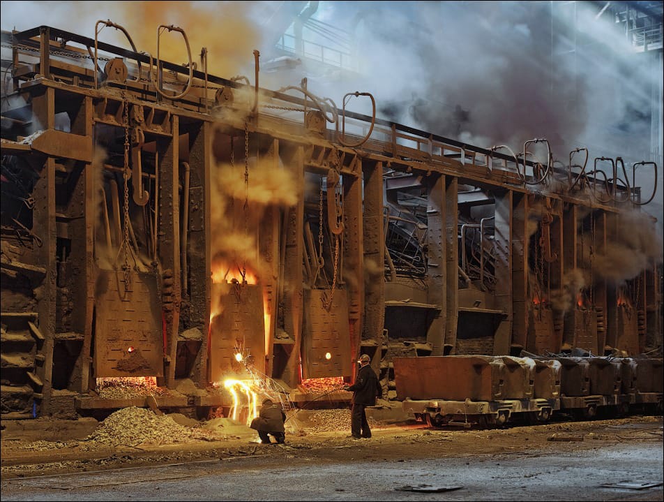
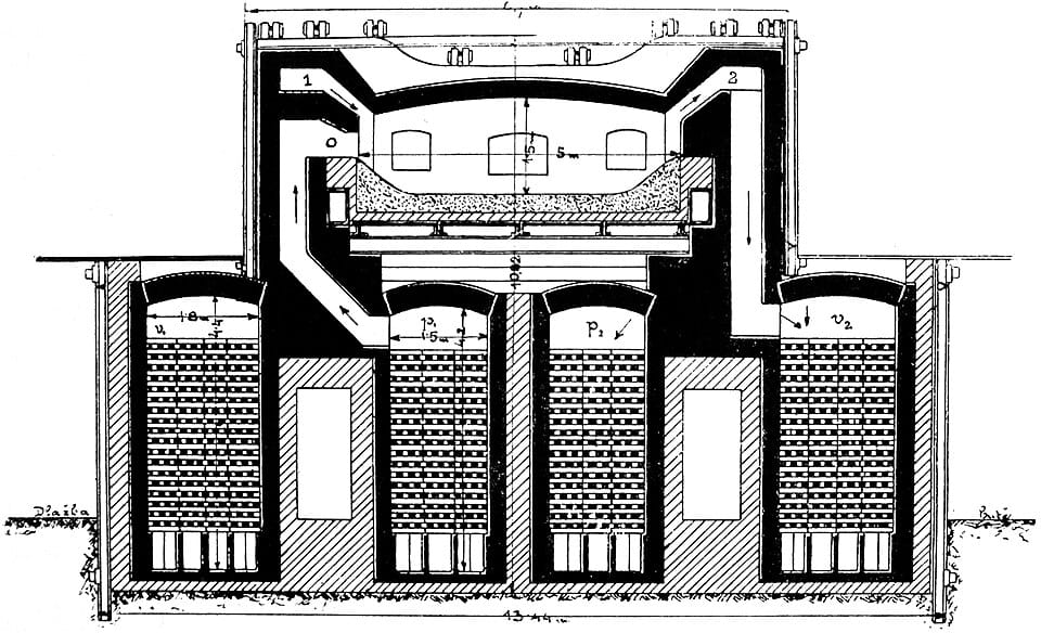
How the regenerators worked
Melting steel asks for more heat than a flame of ordinary fuel and cold air gives. Campbell calls regeneration necessary "because it is impracticable to obtain the necessary temperature in any other way" (Campbell p. 122), and Dichmann says the temperature of a gas flame with cold air is "much under the height which is required for steel production" (Dichmann p. 3). The answer is to catch the heat that would leave up the chimney and hand it back to the gas and air coming in.
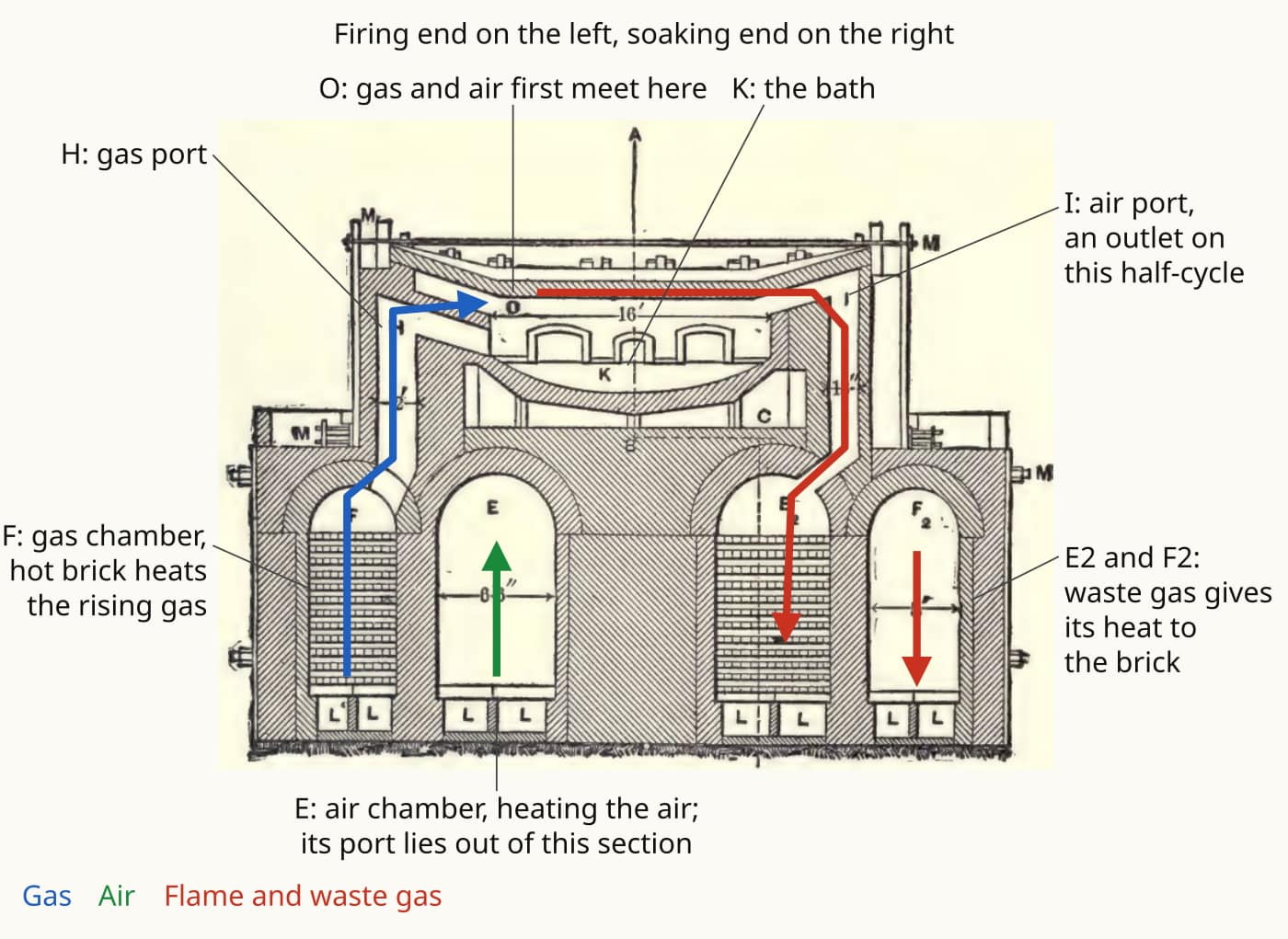
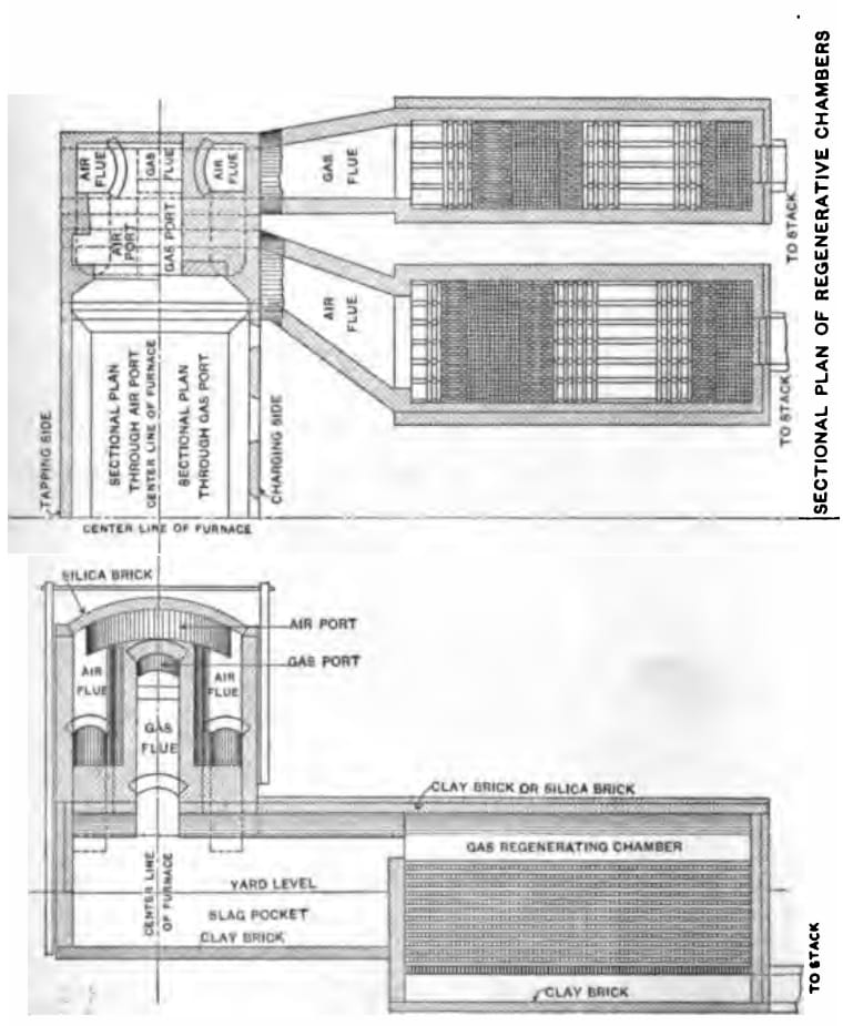
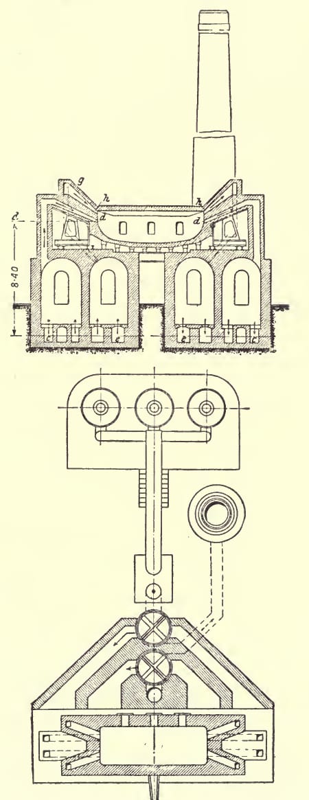
A chamber is a tall brick box filled with brick laid in open rows, so that gas can pass while touching a great deal of surface (Campbell p. 122). There are four: a gas chamber and an air chamber at each end (H-W p. 14; Dichmann p. 6). Waste gas going down through one pair gives them its heat; gas and air coming up through the other pair take it back. When the incoming brick has cooled, valves swap the two ends (Campbell p. 123), every 15 to 20 minutes, right up to the tap (H-W pp. 14-15).
Each reversal starts from brick a little hotter than the last, so the flame is a little hotter too: "the action is cumulative" (Campbell p. 123). Nothing in the furnace stops this climbing except the people running it. The chambers were held about 1000 C (Campbell p. 123), with gas and air reaching about 1200 C and the flame about 1800 C (Dichmann pp. 113-119). The limit is "merely what the brickwork of the furnace will stand" (H-W pp. 14-15); pushed further, "the checkers melt and even the arches of the chambers threaten to sink" (Dichmann p. 117). The roof, of silica brick, was run until it had burned from 9 in. down to 3 in. (H-W pp. 16-18).
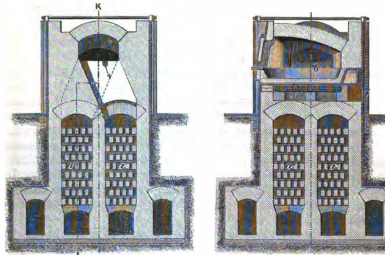
A gas and an air chamber never share brick. The air chamber is the larger, at least 1 1/3 times the gas chamber, about 90 cu ft of chamber for each ton of steel, 13 to 18 ft high on a 60 t furnace (H-W pp. 35-36). Campbell asks for at least 50 cu ft of chequer a ton, and twice that for the best results (Campbell p. 126). Chambers beneath the furnace worked quicker, but a breakout ran metal into the chequers and cracks leaked gas, so by 1909 they stood out at each end, below yard level (H-W p. 34). Vertical chambers were preferred to horizontal ones, because the hot gases rise by themselves and any cold patch evens itself out (Campbell p. 125).
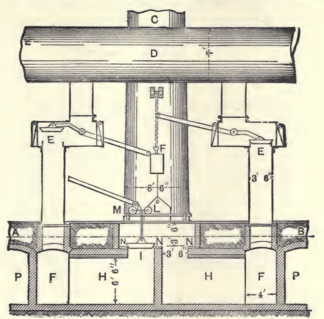
Reversal was done at the valves. The ordinary butterfly valve had a casing with "three openings, one to the stack and one each to the two chambers" (H-W pp. 39-40). Campbell thought it poor: the flap is exposed to the incoming gas on one side and the products of combustion on the other, warps, and leaks gas straight into the chimney (Campbell p. 145). Gas and air were cut for the moment of the swap (Dichmann pp. 136-137).
The gas producer
The fuel for all this was gas, made next door from coal. A gas flame can be regulated at every moment, which a coal fire cannot (Dichmann p. 3), and it was not a rich gas: ordinary producer gas is "over 60 per cent" non-combustible (Campbell p. 123), and it carried about 130 BTU against 1000 to 1100 for natural gas (H-W p. 43). Hot regenerators made that good enough.
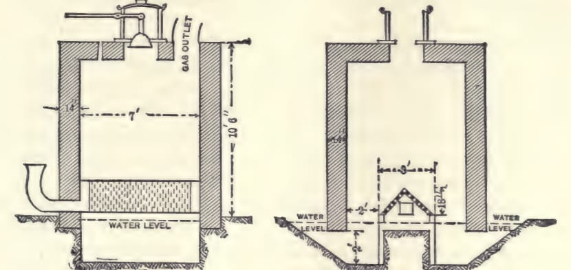
A producer is a shaft of burning fuel kept deliberately short of air (Campbell p. 161). Its bed was about 6 ft deep, in a casing 8 to 12 ft across and 10 to 15 ft high (H-W pp. 44-46). The steam "does not actually add to the calorific efficiency" but keeps the fire low enough that the coal does not clinker (H-W pp. 44-46). Bituminous gas coal was the usual fuel (H-W pp. 47-48); Dichmann's producers burned coal and lignite (Dichmann p. 21).
Why it overtook the converter
A converter makes heat from the metal itself. Its blow took 12 to 20 minutes in 1863 (Percy p. 823) and 7 to 12 by Campbell's time (Campbell pp. 102-108), and its charge had to be of narrow composition (Dichmann p. 3). An open hearth brought its own heat from outside, and that one fact gave it what the converter lacked. It could melt cold scrap and off-grade pig, which the converter could not (Dichmann p. 3). Its bath could be sampled over and over, so less metal was over-oxidised and more ingot came out of it (H-W pp. 13-14). Iron lost in the process was 1.1% against 2.6% (Dichmann p. 312). It was slow: on the same 20 t furnace, 280 minutes on pig and scrap and 315 on scrap with coke (Dichmann pp. 253-254). But the slowness was what allowed a heat to be corrected.
The Siemens brothers' furnace of 1861 came six years after Bessemer's process of 1855 (H-W p. 12), and they ran side by side for decades. Most steel makers, Campbell reports, believed Bessemer steel would do for buildings and highway bridges and wanted open-hearth steel for railway bridges, boilers and locomotive forgings (Campbell pp. 24-25); open-hearth steel was held the more reliable (Campbell pp. 14-15). In the United States the open hearth passed the Bessemer in tonnage in 1908 (H-W pp. 12-13).
Period basis, and what is the game's own
- Period: a gas chamber and an air chamber at each end, the air chamber at least 1 1/3 times the gas chamber, standing clear of the furnace (H-W pp. 14, 34, 35-36). The game plans four chambers outboard of the hearth, the air chamber a third larger, and gas and air never sharing brick.
- Period: a wood fire in one set of chambers until dull red, and gas only after that; cold producer gas can explode (H-W p. 14, Campbell p. 122, Dichmann p. 138). The game plans the same start, with fuel laid in one end's chambers.
- Period: gas admitted through throttles, raised as the charge melts and held at the end (H-W pp. 39-40, Dichmann pp. 129-130), and the stack set by a damper (H-W p. 41). The game plans a gas throttle, an air throttle and a stack damper beside the reversing lever.
- Period: acid practice removes only carbon, silicon and manganese (H-W p. 50), and its slag runs "somewhat under 10 per cent." of the charge (H-W pp. 62-63). The game plans acid practice, no flux, 10% slag.
- Period: a charge without carbon "cannot boil" (Dichmann p. 206), and all-scrap heats worked with coke or anthracite on the bottom (Dichmann pp. 253-254). The game plans a carbon floor on the charge, with coke laid under the scrap counted toward it.
- Period: the producer took air and steam low in the fire, the steam to keep the bed down (H-W pp. 44-46, Campbell p. 161). The game plans a producer fed by a steam jet from the boiler main, so that no boiler means no producer gas and no open hearth. That the jet itself draws the air in is the game's reading; the books have the air blown and the steam admitted.
- The game's own: the furnace is blown. In most real furnaces the air came up through the chambers by its own buoyancy, the gas under producer pressure, with a fan on old furnaces whose chequers had choked (Dichmann pp. 7-16). In the game's heat sum natural draught cannot reach steel's line, so both are driven.
- The game's own: the regenerators are read through the same preheat term as a hot-blast stove, capped at the stove's limit, with no separate model of the brick. See hot blast.
- The game's own: the interval between reversals grows with the chambers' built volume, a simple rule the books do not state.
- The game's own: scrap has no fixed share. Past the carbon floor it costs only time, because the flame keeps the bath hot while cold scrap melts. In the real furnace, charge makeup was a matter of chemistry and judgement (H-W pp. 51-55).
- The game's own: nitrogen is a grade and not a number, and Bessemer steel is barred from the pressure parts by rule. Most steel makers of the period wanted open-hearth steel for boilers (Campbell pp. 24-25), a preference and not a rule.
- The game's own: producer gas is never stored and goes straight down its pipe, and the producer's tar is not modelled, so bituminous and lignite beds make the same clean gas.
The numbers
Every game value is planned, none is built. Heat size and duration are set against the converter, not scaled from period tonnage (see the scaling page and scale and units).
| In the game | Period figure | How it was scaled | Game value |
|---|---|---|---|
| Heat size | 65 to 90 t for the usual 60 t furnace (H-W p. 16) | The game's own, four times the converter | Planned 24,000 u |
| Length of a heat | 280 to 315 minutes (Dichmann pp. 253-254) | The game's own, set by rhythm against the converter | Planned about 54 minutes working, about 60 a cycle |
| Reversal | Every 15 to 20 minutes (H-W pp. 14-15); at least twice an hour (Campbell p. 145) | The game's own | Planned 300 s at the smallest chambers, longer as they grow |
| Chambers, air to gas | At least 1 1/3 to 1 (H-W pp. 35-36) | The rule at face value | Planned air chamber a third larger |
| Preheat | Chambers about 1000 C (Campbell p. 123), gas and air about 1200 C (Dichmann pp. 113-119) | The hot-blast stove's cap, shared | Planned 1240 C |
| Heat at the bath | Flame about 1800 C (Dichmann pp. 113-119) | The game's own heat sum | Planned 2072 C on hot gas and air; 1645 C on cold air |
| Slag | "somewhat under 10 per cent." of the charge (H-W pp. 62-63) | The figure at face value | Planned 10% |
| Scrap in the charge | 25% abroad, 50 to 75% in the United States (H-W pp. 51-55); 70% typical (Dichmann p. 187) | No fixed share | Planned carbon floor, no scrap limit |
| Gas and air draw | None given | The game's own | Planned 24 L/s each at full throttle |
Open, and what you can tell us
The books used here give chamber volumes and reversal intervals, but not a rule joining them, and the game's lengthening of the interval with the chambers is a guess at that relationship. If you know a source that ties the interval to the size of the chequer, or how often an early furnace of the 1860s was reversed, we would like to read it.
Picture credits
- Prace na martinske peci: Viktor Macha, 2012, CC BY-SA 4.0.
- Siemens-Martin furnace, longitudinal section: Otto's Encyclopedia (Ottuv slovnik naucny, 1908), public domain.
- Figs. VIII-A, VIII-H and IX-A: Campbell, The Manufacture and Properties of Iron and Steel, pp. 124, 145 and 161, Library page. The labels and arrows on Fig. VIII-A were drawn for this site from Campbell pp. 122-123.
- Figs. 171 and 172: Percy, Metallurgy: Iron and Steel, p. 683, Library page.
- The plate Modern Open Hearth Furnace: H-W p. 10, Library page.
- Fig. 1A: Dichmann, The Basic Open-Hearth Steel Process, p. 5, Library page.
Comment or suggest something in the Expanded thread on the Vintage Story Discord